Product Description
Product Descriptio
| Product Name | sinotruk howo/shacman spare parts |
| Application | sinotruk howo/shacman heavy duty trucks |
| Warranty | 6 months |
| Material | Metal, plastic, and other |
| Package | Customised |
In order to achieve better quality control, we have our own
warehouse now, it can be a good guarantee from the accuracy
of spare parts, the firmness of packaging, and the timeliness of
delivery.We keep the original packaging, and use plastic film and
wooden boxes etc for wateroroor and anti-collision reinforce-
ment; Make reasonable use of the space, to save unnecessary
transportation costs for customers.
We keep the original packaging, and use plastic film and
wooden boxes etc for waterproof and anti-collision reinforce-
ment; Make reasonable use of the space, to save unnecessary
transportation costs for customers.
1. OEM Manufacturing welcome: Product, Pack-
age…
2. Sample order
3. We will reply you for your inquiry in 24 hours.
4. after sending, we will track the products for you
once every 2 days, until you get the products.
When you got the
goods, test them, and give me a feedback. If you
have any questions about the problem, contact with
us, we will offer
Who we are?
The most professional truck and spare parts manufacturer in China;
The leading truck and spare parts exporter in China;
‘The most comprehensive truck and spare parts solution provider in China;
The most worry-free and most satisfactory and reputable supplier for you in China,
We can never let you down if you choose us.
Frequently Asked Questions
Q1. What are your packing terms?
A: Generally, we pack goods in neutral cartons and wooden crates. We can also pack goods according to your requirements, including outer packaging and various labels.
Q2. What is your delivery time?
A: Generally, it takes 5 to 7 working days after receiving your prepayment. The exact delivery time depends on the items and quantity of your order.
Q3. What is your payment method?
A: Usually T/T, L/C or Western Union,
T/T, L/C or Western Union, 30% as deposit and 70% before delivery. Before you pay the balance, we will show you photos of the products and packaging.
Q4. Can you produce according to samples?
A: Yes, we can produce according to your samples or technical drawings.
Q5. Do you test all goods before delivery?
A: Yes, but you are always welcome to test the goods at our company before delivery.
Q6. How do you build a long term good business relationship with us?
A:1. We keep good quality and competitive price to ensure the benefit of our customers;
2. HangZhou CHINAMFG Automobile Trading Co., Ltd. is a professional, modernized and comprehensive enterprise integrating the assembly, wholesale and export of heavy trucks (especially China Heavy Duty Trucks) and all kinds of accessories for trucks, spare parts for construction machinery, steel as well as construction materials: 1). Heavy-duty truck parts: China National Heavy Duty Truck (Howo, Steyr, Sitrak, Hoyun, Hawker, A7, T7H, etc.), Shakman (Delong), Doofeng, FAW, Beiben, Weichai, Yuchai, Shangchai, engine parts. 2). Construction Machinery: LiuGong, Lingong, LongGong and so on. Our company always adheres to the business policy of taking integrity as the purpose, quality as the life, and service as the leader.
We warmly welcome customers and friends at home and abroad to visit us. CHINAMFG people sincerely look CHINAMFG to cooperating with you to create a bright future!
/* January 22, 2571 19:08:37 */!function(){function s(e,r){var a,o={};try{e&&e.split(“,”).forEach(function(e,t){e&&(a=e.match(/(.*?):(.*)$/))&&1
| After-sales Service: | Video Technical Support, Online Support |
|---|---|
| Warranty: | 6 Months |
| Type: | Chassis |
| Certification: | ISO9001 |
| Driving System Parts: | Frame |
| Electrical System Parts: | Lighting |
| Samples: |
US$ 100/Piece
1 Piece(Min.Order) | |
|---|
Can you explain the role of bearings in conjunction with trailer spindles in towing systems?
Trailer bearings play a critical role in conjunction with trailer spindles in towing systems. Here’s an explanation of their role:
Trailer bearings are components that facilitate the smooth rotation of the trailer wheels around the spindles. They are located within the hub assembly and provide a low-friction interface between the stationary spindle and the rotating wheel. The bearings allow the trailer wheels to rotate freely while supporting the weight of the trailer and its cargo.
The primary functions of bearings in conjunction with trailer spindles are:
- Load Support: Bearings bear the weight of the trailer and its cargo, transferring the load from the axle to the wheels. They distribute the load evenly across the spindle, preventing excessive stress on any specific area and ensuring optimal load capacity.
- Reducing Friction: Bearings minimize friction between the stationary spindle and the rotating wheel hub. By providing a smooth, low-friction interface, they allow the wheels to rotate freely with minimal resistance. This reduces energy consumption and promotes efficient towing.
- Alignment and Stability: Bearings help maintain proper alignment and stability of the trailer wheels. They ensure that the wheels rotate in a straight line and prevent wobbling or uneven tire wear. This is crucial for safe and controlled towing, as improper wheel alignment can lead to handling issues and compromised stability.
- Shock Absorption: Bearings also play a role in absorbing shocks and vibrations encountered during towing. They provide a cushioning effect, reducing the impact of bumps and irregularities on the trailer wheels. This helps improve overall ride comfort and protects the trailer and its contents from excessive jolts or vibrations.
- Lubrication: Properly lubricated bearings reduce friction and heat generation. They also help prevent premature wear and damage to the bearing surfaces. Lubrication ensures smooth operation and extends the lifespan of the bearings and the overall functionality of the towing system.
It’s important to note that trailer bearings require regular maintenance, including inspection, cleaning, and lubrication, to ensure their optimal performance and longevity. Neglecting bearing maintenance can lead to overheating, premature wear, and ultimately, bearing failure, which can result in costly repairs and unsafe towing conditions.
When selecting bearings for trailer spindles, it’s crucial to choose high-quality bearings that are appropriate for the load capacity and towing conditions. It’s recommended to follow the manufacturer’s guidelines regarding bearing specifications, lubrication intervals, and maintenance procedures to ensure proper functioning of the bearings in conjunction with the trailer spindles.
In summary, trailer bearings are essential components in towing systems that work in conjunction with trailer spindles. They support the load, reduce friction, maintain alignment and stability, absorb shocks, and require regular maintenance to ensure optimal functionality and safe towing operations.
What maintenance practices are recommended for trailer spindles to ensure optimal functionality?
Proper maintenance of trailer spindles is essential to ensure their optimal functionality and extend their lifespan. Here are some recommended maintenance practices:
- Regular Inspections: Conduct regular visual inspections of the trailer spindles to check for any signs of damage, wear, or corrosion. Look for cracks, bends, or excessive rust that may compromise the spindle’s integrity. Inspect the spindle nuts, bearings, and seals for proper alignment and condition.
- Lubrication: Proper lubrication is crucial for smooth spindle operation and minimizing friction. Follow the manufacturer’s recommendations for lubrication intervals and use a high-quality grease suitable for trailer spindles. Apply grease to the bearings and spindle surfaces as per the instructions, ensuring even distribution.
- Bearing Maintenance: Inspect and repack the wheel bearings regularly to prevent overheating and premature wear. Clean the bearings and races thoroughly, remove old grease, and repack them with fresh grease. Replace worn or damaged bearings promptly to avoid potential failures.
- Seal Inspection: Check the condition of the spindle seals to ensure they provide adequate protection against dirt, water, and contaminants. Replace damaged or worn seals to maintain proper lubrication and prevent moisture ingress, which can lead to bearing damage.
- Torque Checks: Periodically check and adjust the torque of the spindle nuts to ensure proper bearing adjustment. Follow the manufacturer’s specifications for the recommended torque values and tightening sequence. Over-tightened or loose spindle nuts can lead to bearing damage and compromised spindle performance.
- Brake System Maintenance: If the trailer has brake spindles, inspect and maintain the brake system components as per the manufacturer’s recommendations. Check the brake pads, calipers, and brake lines for wear, damage, or leaks. Keep the braking system clean and adjust the brakes as necessary for optimal stopping performance.
- Protection from Environmental Elements: Protect the spindles from harsh environmental conditions, such as excessive moisture, saltwater, or chemicals. If the trailer is exposed to these elements, consider using protective coatings or covers to minimize corrosion and damage.
- Professional Servicing: For complex maintenance tasks or if you’re unsure about any specific maintenance procedure, it’s recommended to seek professional servicing. Trained technicians can perform comprehensive inspections, bearing replacements, or other specialized maintenance tasks to ensure the optimal functionality of the trailer spindles.
Following these maintenance practices will help ensure the optimal functionality and longevity of trailer spindles. Regular inspections, proper lubrication, bearing maintenance, seal inspections, torque checks, brake system maintenance, protection from environmental elements, and professional servicing when needed are all important steps in maintaining trailer spindles in good working condition.
Remember to consult the trailer manufacturer’s guidelines and recommendations for specific maintenance requirements and intervals based on the spindle type and trailer model.
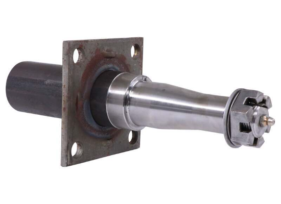
What is a trailer spindle, and what role does it play in a trailer’s construction?
A trailer spindle is a crucial component in the construction of a trailer. It serves a vital role in supporting and facilitating the movement of the trailer’s wheels. Here’s a detailed explanation of what a trailer spindle is and its significance in a trailer’s construction:
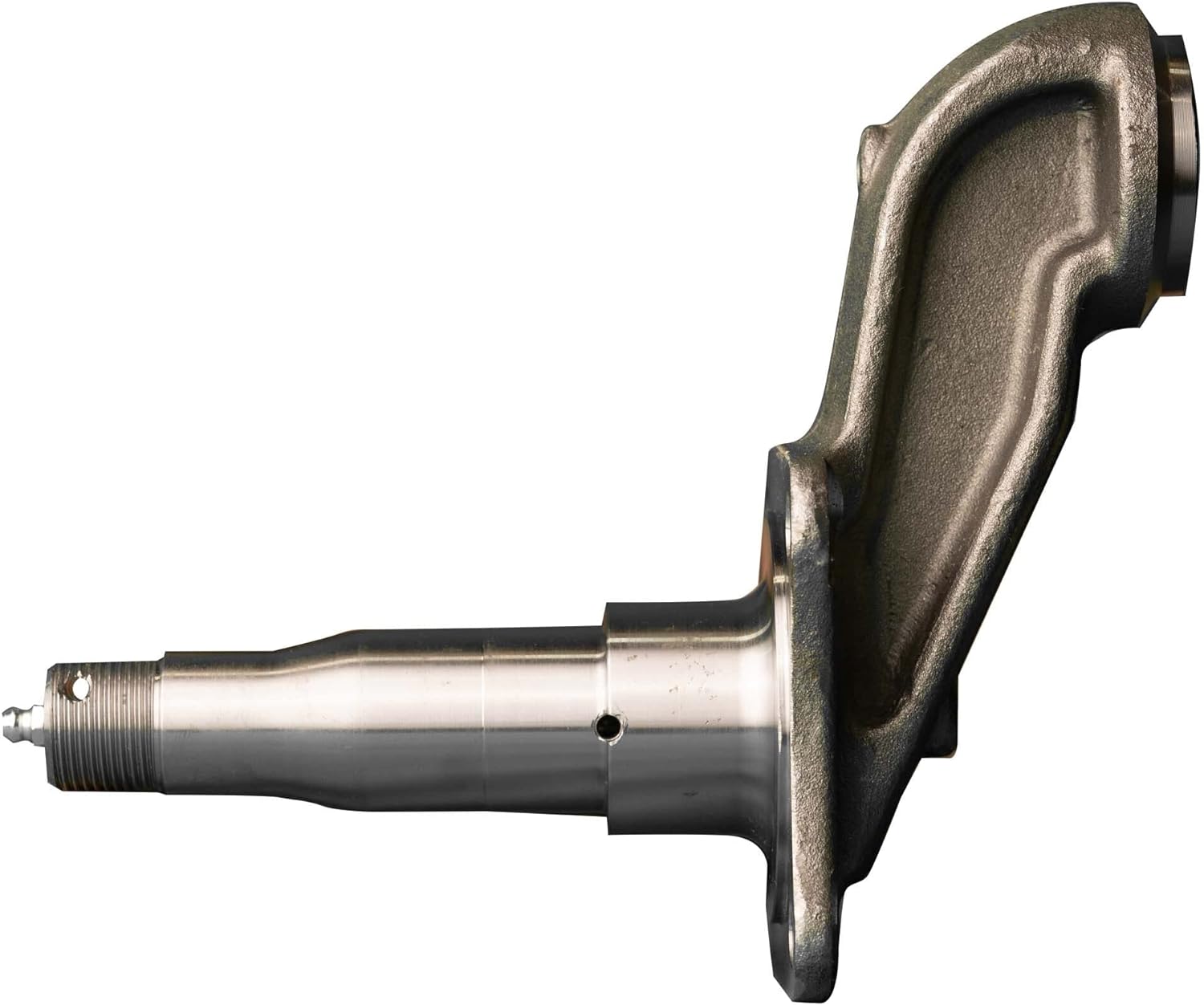
A trailer spindle is a shaft-like component that connects the trailer axle to the wheel hub. It is typically made of high-strength steel and is responsible for supporting the weight of the trailer and facilitating the rotation of the wheels. The spindle is mounted within the wheel hub assembly and allows the wheel to rotate smoothly and securely.
The trailer spindle performs several important functions:
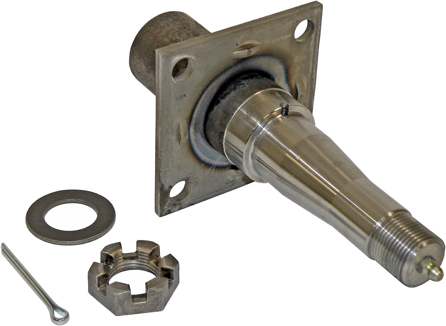
- Wheel Attachment: The spindle provides a secure attachment point for the trailer wheels. It is designed to fit into the wheel hub assembly and is often tapered to ensure a tight and reliable connection. The wheel is typically mounted on the spindle using lug nuts or bolts, which secure it in place.
- Load Bearing: The trailer spindle bears the weight of the trailer and its cargo. It transfers the load from the trailer’s frame and axle to the wheels, distributing the weight evenly across the axle. The spindle must be strong enough to withstand the weight and forces exerted on the wheels during trailer operation.
- Wheel Rotation: The spindle allows the trailer wheels to rotate freely. As the trailer moves, the spindle transfers the rotational force from the axle to the wheel hub, enabling the wheels to spin. This rotation is essential for the trailer’s mobility and maneuverability.
- Lubrication and Heat Dissipation: Some trailer spindles incorporate grease or oil seals and fittings to allow for lubrication. Proper lubrication reduces friction and wear between the spindle and the wheel hub, enhancing the overall performance and lifespan of the trailer’s wheels. Additionally, the spindle’s design facilitates heat dissipation, helping to prevent excessive heat buildup that can lead to component failure.
In summary, a trailer spindle is a vital component in a trailer’s construction. It serves as the connection between the axle and the wheel hub, providing a secure attachment point for the wheels and supporting the weight of the trailer. The spindle enables the wheels to rotate freely, facilitating the trailer’s mobility. It may also incorporate features for lubrication and heat dissipation to ensure proper functioning and longevity of the trailer’s wheels. Overall, the trailer spindle plays a critical role in maintaining the stability, safety, and performance of the trailer during operation.


editor by Dream 2024-05-07
China best Planetary Gearbox Spur Gear Shaft for Wind Turbine with Good quality
Product Description
Planetary Gearbox Spur Gear Shaft for Wind Turbine
Machining Capability
Our Gear, Pinion Shaft, Ring Gear Capabilities:
| Capabilities of Gears/ Splines | ||||||
| Item | Internal Gears and Internal Splines | External Gears and External Splines | ||||
| Milled | Shaped | Ground | Hobbed | Milled | Ground | |
| Max O.D. | 2500 mm | |||||
| Min I.D.(mm) | 30 | 320 | 20 | |||
| Max Face Width(mm) | 500 | 1480 | ||||
| Max DP | 1 | 0.5 | 1 | 0.5 | ||
| Max Module(mm) | 26 | 45 | 26 | 45 | ||
| DIN Class Level | DIN Class 8 | DIN Class 4 | DIN Class 8 | DIN Class 4 | ||
| Tooth Finish | Ra 3.2 | Ra 0.6 | Ra 3.2 | Ra 0.6 | ||
| Max Helix Angle | ±22.5° | ±45° | ||||
Our Main Product Range
1. Spur Gear
2. Planetary Gear
3. Metal Gears
4. Gear Wheel
5. Ring Gear
6. Gear Shaft
7. Helical Gear
8. Pinion Shaft
9. Spline Shaft
Company Profile
1. 21 years experience in high quality gear, gear shaft’s production, sales and R&D.
2. Our Gear, Gear Shaft are certificated by ISO9001: 2008 and ISO14001: 2004.
3. CZPT has more than 50 patents in high quality Gear, Gear Shaft manufacturing.
4. CZPT products are exported to America, Europe.
5. Experience in cooperate with many Fortune 500 Companies
Our Advantages
1) In-house capability: OEM service as per customers’ requests, with in-house tooling design & fabricating
2) Professional engineering capability: On product design, optimization and performance analysis
3) Manufacturing capability range: DIN 3960 class 8 to 4, ISO 1328 class 8 to 4, AGMA 2000 class 10-15, JIS 1702-1703 class 0 to 2, etc.
4) Packing: Tailor-made packaging method according to customer’s requirement
5) Just-in-time delivery capability
FAQ
1. Q: Can you make as per custom drawing?
A: Yes, we can do that.
2. Q: If I don’t have drawing, what can you do for me?
A: If you don’t have drawing, but have the sample part, you may send us. We will check if we can make it or not.
3. Q: How do you make sure the quality of your products?
A: We will do a series of inspections, such as:
A. Raw material inspection (includes chemical and physical mechanical characters inspection),
B. Machining process dimensional inspection (includes: 1st pc inspection, self inspection, final inspection),
C. Heat treatment result inspection,
D. Gear tooth inspection (to know the achieved gear quality level),
E. Magnetic particle inspection (to know if there’s any cracks in the gear).
We will provide you the reports 1 set for each batch/ shipment.
| Material: | 17CrNiMo6 |
|---|---|
| Load: | Drive Shaft |
| Stiffness & Flexibility: | Stiffness / Rigid Axle |
| Customization: |
Available
| Customized Request |
|---|
.shipping-cost-tm .tm-status-off{background: none;padding:0;color: #1470cc}
|
Shipping Cost:
Estimated freight per unit. |
about shipping cost and estimated delivery time. |
|---|
| Payment Method: |
|
|---|---|
|
Initial Payment Full Payment |
| Currency: | US$ |
|---|
| Return&refunds: | You can apply for a refund up to 30 days after receipt of the products. |
|---|

The Benefits of Spline Couplings for Disc Brake Mounting Interfaces
Spline couplings are commonly used for securing disc brake mounting interfaces. Spline couplings are often used in high-performance vehicles, aeronautics, and many other applications. However, the mechanical benefits of splines are not immediately obvious. Listed below are the benefits of spline couplings. We’ll discuss what these advantages mean for you. Read on to discover how these couplings work.
Disc brake mounting interfaces are splined
There are two common disc brake mounting interfaces – splined and six-bolt. Splined rotors fit on splined hubs; six-bolt rotors will need an adapter to fit on six-bolt hubs. The six-bolt method is easier to maintain and may be preferred by many cyclists. If you’re thinking of installing a disc brake system, it is important to know how to choose the right splined and center lock interfaces.
Aerospace applications
The splines used for spline coupling in aircraft are highly complex. While some previous researches have addressed the design of splines, few publications have tackled the problem of misaligned spline coupling. Nevertheless, the accurate results we obtained were obtained using dedicated simulation tools, which are not commercially available. Nevertheless, such tools can provide a useful reference for our approach. It would be beneficial if designers could use simple tools for evaluating contact pressure peaks. Our analytical approach makes it possible to find answers to such questions.
The design of a spline coupling for aerospace applications must be accurate to minimize weight and prevent failure mechanisms. In addition to weight reduction, it is necessary to minimize fretting fatigue. The pressure distribution on the spline coupling teeth is a significant factor in determining its fretting fatigue. Therefore, we use analytical and experimental methods to examine the contact pressure distribution in the axial direction of spline couplings.
The teeth of a spline coupling can be categorized by the type of engagement they provide. This study investigates the position of resultant contact forces in the teeth of a spline coupling when applied to pitch diameter. Using FEM models, numerical results are generated for nominal and parallel offset misalignments. The axial tooth profile determines the behavior of the coupling component and its ability to resist wear. Angular misalignment is also a concern, causing misalignment.
In order to assess wear damage of a spline coupling, we must take into consideration the impact of fretting on the components. This wear is caused by relative motion between the teeth that engage them. The misalignment may be caused by vibrations, cyclical tooth deflection, or angular misalignment. The result of this analysis may help designers improve their spline coupling designs and develop improved performance.
CZPT polyimide, an abrasion-resistant polymer, is a popular choice for high-temperature spline couplings. This material reduces friction and wear, provides a low friction surface, and has a low wear rate. Furthermore, it offers up to 50 times the life of metal on metal spline connections. For these reasons, it is important to choose the right material for your spline coupling.
High-performance vehicles
A spline coupler is a device used to connect splined shafts. A typical spline coupler resembles a short pipe with splines on either end. There are two basic types of spline coupling: single and dual spline. One type attaches to a drive shaft, while the other attaches to the gearbox. While spline couplings are typically used in racing, they’re also used for performance problems.
The key challenge in spline couplings is to determine the optimal dimension of spline joints. This is difficult because no commercial codes allow the simulation of misaligned joints, which can destroy components. This article presents analytical approaches to estimating contact pressures in spline connections. The results are comparable with numerical approaches but require special codes to accurately model the coupling operation. This research highlights several important issues and aims to make the application of spline couplings in high-performance vehicles easier.
The stiffness of spline assemblies can be calculated using tooth-like structures. Such splines can be incorporated into the spline joint to produce global stiffness for torsional vibration analysis. Bearing reactions are calculated for a certain level of misalignment. This information can be used to design bearing dimensions and correct misalignment. There are three types of spline couplings.
Major diameter fit splines are made with tightly controlled outside diameters. This close fit provides concentricity transfer from the male to the female spline. The teeth of the male spline usually have chamfered tips and clearance with fillet radii. These splines are often manufactured from billet steel or aluminum. These materials are renowned for their strength and uniform grain created by the forging process. ANSI and DIN design manuals define classes of fit.
Disc brake mounting interfaces
A spline coupling for disc brake mounting interfaces is a type of hub-to-brake-disc mount. It is a highly durable coupling mechanism that reduces heat transfer from the disc to the axle hub. The mounting arrangement also isolates the axle hub from direct contact with the disc. It is also designed to minimize the amount of vehicle downtime and maintenance required to maintain proper alignment.
Disc brakes typically have substantial metal-to-metal contact with axle hub splines. The discs are held in place on the hub by intermediate inserts. This metal-to-metal contact also aids in the transfer of brake heat from the brake disc to the axle hub. Spline coupling for disc brake mounting interfaces comprises a mounting ring that is either a threaded or non-threaded spline.
During drag brake experiments, perforated friction blocks filled with various additive materials are introduced. The materials included include Cu-based powder metallurgy material, a composite material, and a Mn-Cu damping alloy. The filling material affects the braking interface’s wear behavior and friction-induced vibration characteristics. Different filling materials produce different types of wear debris and have different wear evolutions. They also differ in their surface morphology.
Disc brake couplings are usually made of two different types. The plain and HD versions are interchangeable. The plain version is the simplest to install, while the HD version has multiple components. The two-piece couplings are often installed at the same time, but with different mounting interfaces. You should make sure to purchase the appropriate coupling for your vehicle. These interfaces are a vital component of your vehicle and must be installed correctly for proper operation.
Disc brakes use disc-to-hub elements that help locate the forces and displace them to the rim. These elements are typically made of stainless steel, which increases the cost of manufacturing the disc brake mounting interface. Despite their benefits, however, the high braking force loads they endure are hard on the materials. Moreover, excessive heat transferred to the intermediate elements can adversely affect the fatigue life and long-term strength of the brake system.


editor by CX 2023-11-08
China wholesaler Worm Gear Drive Wheel Good Price Ground Shaft Helical Micro for Gearbox Speed Reducer Outdoor Ride Car Spare Part Worm Gear with Good quality
Product Description
Our Advantages
Our advantange, Low MOQ as less as 1 piece, 100% inspection, Short Lead time.
Our service
We manufacture various shafts made according to drawing, including roud shaft, square shaft, hollow shaft, screw shaft, spline shaft, gear shaft, etc.
| Material | Alloy, stainless steel, Carbon steel, etc. |
| Mahines | NC lathe, Milling macine, Ginder, CNC, Gear milling machine. |
| Third party inspection | Available, SGS, CNAS, BV, etc. |
| UT standard | ASTM A388, AS1065, GB/T6402, etc. |
| Packaging | Seaworthy packing |
| Drawing format | PDF, DWG, DXF, STP, IGS, etc. |
| Application | Industry usage, Machine usage. |
| MOQ | 1 piece |
| Drawing format | PDF, DWG, DXF, STP, IGS, etc. |
| Quotation time | 1 days. |
| Lead time | Generaly 30-40 days for mass production. |
Our Product
During the pass 10 years, we have supplied hundreds of customers with perfect precision machining jobs:
Workshop & machining process
We manufacture various shafts made according to drawing, including roud shaft, square shaft, hollow shaft, screw shaft, spline shaft, gear shaft, etc.
FAQ
Q: Are you treading company or manufacturer?
A: We are manufacturer.
Q: How about your MOQ?
A: We provide both prototype and mass production, Our MOQ is 1 piece.
Q:How long can I get a quote after RFQ?
A:we generally quote you within 24 hours. More detail information provided will be helpful to save your time.
1) detailed engineering drawing with tolerance and other requirement.
2) the quantity you demand.
Q:How is your quality guarantee?
A:we do 100% inspection before delivery, we are looking for long term business relationship.
Q:Can I CZPT NDA with you?
A:Sure, we will keep your drawing and information confidential.
| Casting Method: | Thermal Gravity Casting |
|---|---|
| Process: | CNC |
| Molding Technics: | Gravity Casting |
| Application: | Machinery Parts |
| Material: | Carbon Steel |
| Surface Preparation: | Polishing |
| Samples: |
US$ 2/Piece
1 Piece(Min.Order) | |
|---|
| Customization: |
Available
| Customized Request |
|---|

How to Calculate Stiffness, Centering Force, Wear and Fatigue Failure of Spline Couplings
There are various types of spline couplings. These couplings have several important properties. These properties are: Stiffness, Involute splines, Misalignment, Wear and fatigue failure. To understand how these characteristics relate to spline couplings, read this article. It will give you the necessary knowledge to determine which type of coupling best suits your needs. Keeping in mind that spline couplings are usually spherical in shape, they are made of steel.
Involute splines
An effective side interference condition minimizes gear misalignment. When two splines are coupled with no spline misalignment, the maximum tensile root stress shifts to the left by five mm. A linear lead variation, which results from multiple connections along the length of the spline contact, increases the effective clearance or interference by a given percentage. This type of misalignment is undesirable for coupling high-speed equipment.
Involute splines are often used in gearboxes. These splines transmit high torque, and are better able to distribute load among multiple teeth throughout the coupling circumference. The involute profile and lead errors are related to the spacing between spline teeth and keyways. For coupling applications, industry practices use splines with 25 to fifty-percent of spline teeth engaged. This load distribution is more uniform than that of conventional single-key couplings.
To determine the optimal tooth engagement for an involved spline coupling, Xiangzhen Xue and colleagues used a computer model to simulate the stress applied to the splines. The results from this study showed that a “permissible” Ruiz parameter should be used in coupling. By predicting the amount of wear and tear on a crowned spline, the researchers could accurately predict how much damage the components will sustain during the coupling process.
There are several ways to determine the optimal pressure angle for an involute spline. Involute splines are commonly measured using a pressure angle of 30 degrees. Similar to gears, involute splines are typically tested through a measurement over pins. This involves inserting specific-sized wires between gear teeth and measuring the distance between them. This method can tell whether the gear has a proper tooth profile.
The spline system shown in Figure 1 illustrates a vibration model. This simulation allows the user to understand how involute splines are used in coupling. The vibration model shows four concentrated mass blocks that represent the prime mover, the internal spline, and the load. It is important to note that the meshing deformation function represents the forces acting on these three components.
Stiffness of coupling
The calculation of stiffness of a spline coupling involves the measurement of its tooth engagement. In the following, we analyze the stiffness of a spline coupling with various types of teeth using two different methods. Direct inversion and blockwise inversion both reduce CPU time for stiffness calculation. However, they require evaluation submatrices. Here, we discuss the differences between these two methods.
The analytical model for spline couplings is derived in the second section. In the third section, the calculation process is explained in detail. We then validate this model against the FE method. Finally, we discuss the influence of stiffness nonlinearity on the rotor dynamics. Finally, we discuss the advantages and disadvantages of each method. We present a simple yet effective method for estimating the lateral stiffness of spline couplings.
The numerical calculation of the spline coupling is based on the semi-analytical spline load distribution model. This method involves refined contact grids and updating the compliance matrix at each iteration. Hence, it consumes significant computational time. Further, it is difficult to apply this method to the dynamic analysis of a rotor. This method has its own limitations and should be used only when the spline coupling is fully investigated.
The meshing force is the force generated by a misaligned spline coupling. It is related to the spline thickness and the transmitting torque of the rotor. The meshing force is also related to the dynamic vibration displacement. The result obtained from the meshing force analysis is given in Figures 7, 8, and 9.
The analysis presented in this paper aims to investigate the stiffness of spline couplings with a misaligned spline. Although the results of previous studies were accurate, some issues remained. For example, the misalignment of the spline may cause contact damages. The aim of this article is to investigate the problems associated with misaligned spline couplings and propose an analytical approach for estimating the contact pressure in a spline connection. We also compare our results to those obtained by pure numerical approaches.
Misalignment
To determine the centering force, the effective pressure angle must be known. Using the effective pressure angle, the centering force is calculated based on the maximum axial and radial loads and updated Dudley misalignment factors. The centering force is the maximum axial force that can be transmitted by friction. Several published misalignment factors are also included in the calculation. A new method is presented in this paper that considers the cam effect in the normal force.
In this new method, the stiffness along the spline joint can be integrated to obtain a global stiffness that is applicable to torsional vibration analysis. The stiffness of bearings can also be calculated at given levels of misalignment, allowing for accurate estimation of bearing dimensions. It is advisable to check the stiffness of bearings at all times to ensure that they are properly sized and aligned.
A misalignment in a spline coupling can result in wear or even failure. This is caused by an incorrectly aligned pitch profile. This problem is often overlooked, as the teeth are in contact throughout the involute profile. This causes the load to not be evenly distributed along the contact line. Consequently, it is important to consider the effect of misalignment on the contact force on the teeth of the spline coupling.
The centre of the male spline in Figure 2 is superposed on the female spline. The alignment meshing distances are also identical. Hence, the meshing force curves will change according to the dynamic vibration displacement. It is necessary to know the parameters of a spline coupling before implementing it. In this paper, the model for misalignment is presented for spline couplings and the related parameters.
Using a self-made spline coupling test rig, the effects of misalignment on a spline coupling are studied. In contrast to the typical spline coupling, misalignment in a spline coupling causes fretting wear at a specific position on the tooth surface. This is a leading cause of failure in these types of couplings.
Wear and fatigue failure
The failure of a spline coupling due to wear and fatigue is determined by the first occurrence of tooth wear and shaft misalignment. Standard design methods do not account for wear damage and assess the fatigue life with big approximations. Experimental investigations have been conducted to assess wear and fatigue damage in spline couplings. The tests were conducted on a dedicated test rig and special device connected to a standard fatigue machine. The working parameters such as torque, misalignment angle, and axial distance have been varied in order to measure fatigue damage. Over dimensioning has also been assessed.
During fatigue and wear, mechanical sliding takes place between the external and internal splines and results in catastrophic failure. The lack of literature on the wear and fatigue of spline couplings in aero-engines may be due to the lack of data on the coupling’s application. Wear and fatigue failure in splines depends on a number of factors, including the material pair, geometry, and lubrication conditions.
The analysis of spline couplings shows that over-dimensioning is common and leads to different damages in the system. Some of the major damages are wear, fretting, corrosion, and teeth fatigue. Noise problems have also been observed in industrial settings. However, it is difficult to evaluate the contact behavior of spline couplings, and numerical simulations are often hampered by the use of specific codes and the boundary element method.
The failure of a spline gear coupling was caused by fatigue, and the fracture initiated at the bottom corner radius of the keyway. The keyway and splines had been overloaded beyond their yield strength, and significant yielding was observed in the spline gear teeth. A fracture ring of non-standard alloy steel exhibited a sharp corner radius, which was a significant stress raiser.
Several components were studied to determine their life span. These components include the spline shaft, the sealing bolt, and the graphite ring. Each of these components has its own set of design parameters. However, there are similarities in the distributions of these components. Wear and fatigue failure of spline couplings can be attributed to a combination of the three factors. A failure mode is often defined as a non-linear distribution of stresses and strains.
editor by CX 2023-10-22
China Metal Transmission Spline Shaft with Alloy Steel Material for Gearbox Reducer Engineering Vehicles Automobiles Ships drive shaft coupler
Condition: New
Guarantee: 6 Months
Applicable Industries: Developing Content Shops, Producing Plant, Machinery Fix Shops, Food & Beverage Factory, Farms, Development works , Energy & Mining
Framework: Spline
Substance: carbon metal, alloy metal , bronze/brass
Coatings: Black Oxide
Torque Potential: Custom-made
Design Number: Personalized
Packaging Information: Neutral paper packaging, picket containers for outer box or according to customer’s demand.
Port: ZheJiang Port / HangZhou Port
:
(1). All types of gears, shaft, gear shaft, precision gear and CNC equipment. (2). Specialized in producing all kinds of auto transmission part primarily based on drawings (3). Content: ductile forged iron, carbon metal, alloy steel , Steel Pintle Chains stainless metal, , bronze/brass (4). Modules: M1 to M8 (5). Satisfies ISO, DIN and ASTM expectations (6). Specification : In accordance to the the drawing
(7). Certification: ISO/TS16949:2T Sprocket Mountain Bike Crank Bottom Bracket BB CHangZhou Slender Extensive Bicycle Established 10S ISO/TS16949:2009
How to Calculate Stiffness, Centering Force, Wear and Fatigue Failure of Spline Couplings
There are various types of spline couplings. These couplings have several important properties. These properties are: Stiffness, Involute splines, Misalignment, Wear and fatigue failure. To understand how these characteristics relate to spline couplings, read this article. It will give you the necessary knowledge to determine which type of coupling best suits your needs. Keeping in mind that spline couplings are usually spherical in shape, they are made of steel.
Involute splines
An effective side interference condition minimizes gear misalignment. When two splines are coupled with no spline misalignment, the maximum tensile root stress shifts to the left by five mm. A linear lead variation, which results from multiple connections along the length of the spline contact, increases the effective clearance or interference by a given percentage. This type of misalignment is undesirable for coupling high-speed equipment.
Involute splines are often used in gearboxes. These splines transmit high torque, and are better able to distribute load among multiple teeth throughout the coupling circumference. The involute profile and lead errors are related to the spacing between spline teeth and keyways. For coupling applications, industry practices use splines with 25 to fifty-percent of spline teeth engaged. This load distribution is more uniform than that of conventional single-key couplings.
To determine the optimal tooth engagement for an involved spline coupling, Xiangzhen Xue and colleagues used a computer model to simulate the stress applied to the splines. The results from this study showed that a “permissible” Ruiz parameter should be used in coupling. By predicting the amount of wear and tear on a crowned spline, the researchers could accurately predict how much damage the components will sustain during the coupling process.
There are several ways to determine the optimal pressure angle for an involute spline. Involute splines are commonly measured using a pressure angle of 30 degrees. Similar to gears, involute splines are typically tested through a measurement over pins. This involves inserting specific-sized wires between gear teeth and measuring the distance between them. This method can tell whether the gear has a proper tooth profile.
The spline system shown in Figure 1 illustrates a vibration model. This simulation allows the user to understand how involute splines are used in coupling. The vibration model shows four concentrated mass blocks that represent the prime mover, the internal spline, and the load. It is important to note that the meshing deformation function represents the forces acting on these three components.
Stiffness of coupling
The calculation of stiffness of a spline coupling involves the measurement of its tooth engagement. In the following, we analyze the stiffness of a spline coupling with various types of teeth using two different methods. Direct inversion and blockwise inversion both reduce CPU time for stiffness calculation. However, they require evaluation submatrices. Here, we discuss the differences between these two methods.
The analytical model for spline couplings is derived in the second section. In the third section, the calculation process is explained in detail. We then validate this model against the FE method. Finally, we discuss the influence of stiffness nonlinearity on the rotor dynamics. Finally, we discuss the advantages and disadvantages of each method. We present a simple yet effective method for estimating the lateral stiffness of spline couplings.
The numerical calculation of the spline coupling is based on the semi-analytical spline load distribution model. This method involves refined contact grids and updating the compliance matrix at each iteration. Hence, it consumes significant computational time. Further, it is difficult to apply this method to the dynamic analysis of a rotor. This method has its own limitations and should be used only when the spline coupling is fully investigated.
The meshing force is the force generated by a misaligned spline coupling. It is related to the spline thickness and the transmitting torque of the rotor. The meshing force is also related to the dynamic vibration displacement. The result obtained from the meshing force analysis is given in Figures 7, 8, and 9.
The analysis presented in this paper aims to investigate the stiffness of spline couplings with a misaligned spline. Although the results of previous studies were accurate, some issues remained. For example, the misalignment of the spline may cause contact damages. The aim of this article is to investigate the problems associated with misaligned spline couplings and propose an analytical approach for estimating the contact pressure in a spline connection. We also compare our results to those obtained by pure numerical approaches.
Misalignment
To determine the centering force, the effective pressure angle must be known. Using the effective pressure angle, the centering force is calculated based on the maximum axial and radial loads and updated Dudley misalignment factors. The centering force is the maximum axial force that can be transmitted by friction. Several published misalignment factors are also included in the calculation. A new method is presented in this paper that considers the cam effect in the normal force.
In this new method, the stiffness along the spline joint can be integrated to obtain a global stiffness that is applicable to torsional vibration analysis. The stiffness of bearings can also be calculated at given levels of misalignment, allowing for accurate estimation of bearing dimensions. It is advisable to check the stiffness of bearings at all times to ensure that they are properly sized and aligned.
A misalignment in a spline coupling can result in wear or even failure. This is caused by an incorrectly aligned pitch profile. This problem is often overlooked, as the teeth are in contact throughout the involute profile. This causes the load to not be evenly distributed along the contact line. Consequently, it is important to consider the effect of misalignment on the contact force on the teeth of the spline coupling.
The centre of the male spline in Figure 2 is superposed on the female spline. The alignment meshing distances are also identical. Hence, the meshing force curves will change according to the dynamic vibration displacement. It is necessary to know the parameters of a spline coupling before implementing it. In this paper, the model for misalignment is presented for spline couplings and the related parameters.
Using a self-made spline coupling test rig, the effects of misalignment on a spline coupling are studied. In contrast to the typical spline coupling, misalignment in a spline coupling causes fretting wear at a specific position on the tooth surface. This is a leading cause of failure in these types of couplings.
Wear and fatigue failure
The failure of a spline coupling due to wear and fatigue is determined by the first occurrence of tooth wear and shaft misalignment. Standard design methods do not account for wear damage and assess the fatigue life with big approximations. Experimental investigations have been conducted to assess wear and fatigue damage in spline couplings. The tests were conducted on a dedicated test rig and special device connected to a standard fatigue machine. The working parameters such as torque, misalignment angle, and axial distance have been varied in order to measure fatigue damage. Over dimensioning has also been assessed.
During fatigue and wear, mechanical sliding takes place between the external and internal splines and results in catastrophic failure. The lack of literature on the wear and fatigue of spline couplings in aero-engines may be due to the lack of data on the coupling’s application. Wear and fatigue failure in splines depends on a number of factors, including the material pair, geometry, and lubrication conditions.
The analysis of spline couplings shows that over-dimensioning is common and leads to different damages in the system. Some of the major damages are wear, fretting, corrosion, and teeth fatigue. Noise problems have also been observed in industrial settings. However, it is difficult to evaluate the contact behavior of spline couplings, and numerical simulations are often hampered by the use of specific codes and the boundary element method.
The failure of a spline gear coupling was caused by fatigue, and the fracture initiated at the bottom corner radius of the keyway. The keyway and splines had been overloaded beyond their yield strength, and significant yielding was observed in the spline gear teeth. A fracture ring of non-standard alloy steel exhibited a sharp corner radius, which was a significant stress raiser.
Several components were studied to determine their life span. These components include the spline shaft, the sealing bolt, and the graphite ring. Each of these components has its own set of design parameters. However, there are similarities in the distributions of these components. Wear and fatigue failure of spline couplings can be attributed to a combination of the three factors. A failure mode is often defined as a non-linear distribution of stresses and strains.
editor by czh 2023-02-19
China OEM 4.5 Tons Forklift Parts Mechanical Transmission Gearbox Manual Shift Type with Best Sales
Product Description
Product Description
Mechanical Transmission Gearbox- QTJD45
Suitable for 4.5tons diesel forklift.
Brand:TCM,HELI,DOOSAN,HANGCHA,TAILIF…..
Characteristics:
1)Sliding (Inertial lock-ring) synchronizer makes the shifting more flexible and has less impact.
2)Because of extensible spindle design, there is no need to disassemble the gearbox when replace the discs.
3)The transmission has good bearing capacity, high transmission efficiency and stable operation.
Product Parameters
| Transmission Model | QTJD45 | |
| Match Engine Rated Power Kw | 44-68 | |
| Match Engine Rotating Speed r/min | 2200~2600 | |
| Match Engine Max Output Moment N.m | 195-340 | |
| Transmission Ratio | Forward 1(F1) | 7.36 |
| Forward 11 (F2) | 2.91 | |
| Backward 1 (R1) | 7.36 | |
| Backward 11 (R2) | 2.91 | |
| Synchronizer Pattern | Inertial lock-ring | |
| Shift Pattern | Manual Shift | |
| Input Shaft Rotating Speed | Clockwise( from input ) | |
| Lubricating Oil | GL-5 80W-90 vehicle gear oil | |
| Oil Capacity | 11-12 | |
| Working Oil TemperatureºC | 60~80 | |
| Top Working Oil TemperatureºC | 120(no more than 5 mins) | |
| Net Weight kg | 197 | |
Our company is specialized in the production of engine gears, gears of transmission, and gears used for various construction machinery and vehicles. Our company owns various kinds of high-grade, precision and advanced machining equipment (photos) which can economically and efficiently machine and produce transmission parts like spur gear, helical gear, multi-link gear, internal gear, small-taper teeth, crowned teeth, sharp and thin teeth, worm gear and chain gear.
Gear machining range:
1.Maximum modulus: 8
2.Maximum outer diameter: φ500
3.Accuracy grade:4 Grade GB/T 10095-2008
Our Advantages
Company Profile
HangZhou Tsingleader Industry Co., Ltd. is located in the beautiful HangZhou city. We specialize in the production of trailer parts, axle and transmission of engineering machinery and special engineering and agricultural machinery.
Over the past years, Tsingleader Industry has invested 4 manufacturing plants in China. Following the principle of “quality assurance, abiding by the contract, reciprocity, mutual benefit and first-class services”, we have won the trust from our clients both at home and abroad.
Our annual sales amount reaches USD 5 million and our products have been exported to North and South America, Europe ,Africa,South Asia and the Middle East.
We sincerely hope to become your earnest business partner and your contact will be warmly welcomed.
What Are the Advantages of a Splined Shaft?
If you are looking for the right splined shaft for your machine, you should know a few important things. First, what type of material should be used? Stainless steel is usually the most appropriate choice, because of its ability to offer low noise and fatigue failure. Secondly, it can be machined using a slotting or shaping machine. Lastly, it will ensure smooth motion. So, what are the advantages of a splined shaft?
Stainless steel is the best material for splined shafts
When choosing a splined shaft, you should consider its hardness, quality, and finish. Stainless steel has superior corrosion and wear resistance. Carbon steel is another good material for splined shafts. Carbon steel has a shallow carbon content (about 1.7%), which makes it more malleable and helps ensure smooth motion. But if you’re not willing to spend the money on stainless steel, consider other options.
There are 2 main types of splines: parallel splines and crowned splines. Involute splines have parallel grooves and allow linear and rotary motion. Helical splines have involute teeth and are oriented at an angle. This type allows for many teeth on the shaft and minimizes the stress concentration in the stationary joint.
Large evenly spaced splines are widely used in hydraulic systems, drivetrains, and machine tools. They are typically made from carbon steel (CR10) and stainless steel (AISI 304). This material is durable and meets the requirements of ISO 14-B, formerly DIN 5463-B. Splined shafts are typically made of stainless steel or C45 steel, though there are many other materials available.
Stainless steel is the best material for a splined shaft. This metal is also incredibly affordable. In most cases, stainless steel is the best choice for these shafts because it offers the best corrosion resistance. There are many different types of splined shafts, and each 1 is suited for a particular application. There are also many different types of stainless steel, so choose stainless steel if you want the best quality.
For those looking for high-quality splined shafts, CZPT Spline Shafts offer many benefits. They can reduce costs, improve positional accuracy, and reduce friction. With the CZPT TFE coating, splined shafts can reduce energy and heat buildup, and extend the life of your products. And, they’re easy to install – all you need to do is install them.
They provide low noise, low wear and fatigue failure
The splines in a splined shaft are composed of 2 main parts: the spline root fillet and the spline relief. The spline root fillet is the most critical part, because fatigue failure starts there and propagates to the relief. The spline relief is more susceptible to fatigue failure because of its involute tooth shape, which offers a lower stress to the shaft and has a smaller area of contact.
The fatigue life of splined shafts is determined by measuring the S-N curve. This is also known as the Wohler curve, and it is the relationship between stress amplitude and number of cycles. It depends on the material, geometry and way of loading. It can be obtained from a physical test on a uniform material specimen under a constant amplitude load. Approximations for low-alloy steel parts can be made using a lower-alloy steel material.
Splined shafts provide low noise, minimal wear and fatigue failure. However, some mechanical transmission elements need to be removed from the shaft during assembly and manufacturing processes. The shafts must still be capable of relative axial movement for functional purposes. As such, good spline joints are essential to high-quality torque transmission, minimal backlash, and low noise. The major failure modes of spline shafts include fretting corrosion, tooth breakage, and fatigue failure.
The outer disc carrier spline is susceptible to tensile stress and fatigue failure. High customer demands for low noise and low wear and fatigue failure makes splined shafts an excellent choice. A fractured spline gear coupling was received for analysis. It was installed near the top of a filter shaft and inserted into the gearbox motor. The service history was unknown. The fractured spline gear coupling had longitudinally cracked and arrested at the termination of the spline gear teeth. The spline gear teeth also exhibited wear and deformation.
A new spline coupling method detects fault propagation in hollow cylindrical splined shafts. A spline coupling is fabricated using an AE method with the spline section unrolled into a metal plate of the same thickness as the cylinder wall. In addition, the spline coupling is misaligned, which puts significant concentration on the spline teeth. This further accelerates the rate of fretting fatigue and wear.
A spline joint should be lubricated after 25 hours of operation. Frequent lubrication can increase maintenance costs and cause downtime. Moreover, the lubricant may retain abrasive particles at the interfaces. In some cases, lubricants can even cause misalignment, leading to premature failure. So, the lubrication of a spline coupling is vital in ensuring proper functioning of the shaft.
The design of a spline coupling can be optimized to enhance its wear resistance and reliability. Surface treatments, loads, and rotation affect the friction properties of a spline coupling. In addition, a finite element method was developed to predict wear of a floating spline coupling. This method is feasible and provides a reliable basis for predicting the wear and fatigue life of a spline coupling.
They can be machined using a slotting or shaping machine
Machines can be used to shape splined shafts in a variety of industries. They are useful in many applications, including gearboxes, braking systems, and axles. A slotted shaft can be manipulated in several ways, including hobbling, broaching, and slotting. In addition to shaping, splines are also useful in reducing bar diameter.
When using a slotting or shaping machine, the workpiece is held against a pedestal that has a uniform thickness. The machine is equipped with a stand column and limiting column (Figure 1), each positioned perpendicular to the upper surface of the pedestal. The limiting column axis is located on the same line as the stand column. During the slotting or shaping process, the tool is fed in and out until the desired space is achieved.
One process involves cutting splines into a shaft. Straddle milling, spline shaping, and spline cutting are 2 common processes used to create splined shafts. Straddle milling involves a fixed indexing fixture that holds the shaft steady, while rotating milling cutters cut the groove in the length of the shaft. Several passes are required to ensure uniformity throughout the spline.
Splines are a type of gear. The ridges or teeth on the drive shaft mesh with grooves in the mating piece. A splined shaft allows the transmission of torque to a mate piece while maximizing the power transfer. Splines are used in heavy vehicles, construction, agriculture, and massive earthmoving machinery. Splines are used in virtually every type of rotary motion, from axles to transmission systems. They also offer better fatigue life and reliability.
Slotting or shaping machines can also be used to shape splined shafts. Slotting machines are often used to machine splined shafts, because it is easier to make them with these machines. Using a slotting or shaping machine can result in splined shafts of different sizes. It is important to follow a set of spline standards to ensure your parts are manufactured to the highest standards.
A milling machine is another option for producing splined shafts. A spline shaft can be set up between 2 centers in an indexing fixture. Two side milling cutters are mounted on an arbor and a spacer and shims are inserted between them. The arbor and cutters are then mounted to a milling machine spindle. To make sure the cutters center themselves over the splined shaft, an adjustment must be made to the spindle of the machine.
The machining process is very different for internal and external splines. External splines can be broached, shaped, milled, or hobbed, while internal splines cannot. These machines use hard alloy, but they are not as good for internal splines. A machine with a slotting mechanism is necessary for these operations.
China manufacturer Forklift Mechanical Transmission Gearbox for 4 Tons-5 Tons Diesel Forklift with Best Sales
Product Description
Product Description
Mechanical Transmission Gearbox- QTJH400 / QTJH470
Suitable for 4tons – 5 tons diesel forklift.
Brand:TCM,HELI,DOOSAN,HANGCHA,TAILIF…..
Characteristics:
1)Sliding (Inertial lock-ring) synchronizer makes the shifting more flexible and has less impact.
2)Because of extensible spindle design, there is no need to disassemble the gearbox when replace the discs.
3)The transmission has good bearing capacity, high transmission efficiency and stable operation.
Product Parameters
| Transmission Model | QTJH400 | QTJH470 |
| Engine Rated Power(kw) | 45~50 | 45~74 |
| Engine Rated Rotating Speed (r/min) | 1800~2400 | 2200~2650 |
| Engine Max Torque(N.m) | 193~371 | 193~371 |
| Transmission Gear Ratio | F1=9.28 F2=4.804 F3=3.007 |
F1=9.333 F2=4.973 F3=2.823 |
| R1=8.767 R2=4.232 |
R1=8.487 R2=4.68 |
Our company is specialized in the production of engine gears, gears of transmission, and gears used for various construction machinery and vehicles. Our company owns various kinds of high-grade, precision and advanced machining equipment (photos) which can economically and efficiently machine and produce transmission parts like spur gear, helical gear, multi-link gear, internal gear, small-taper teeth, crowned teeth, sharp and thin teeth, worm gear and chain gear.
Gear machining range:
1.Maximum modulus: 8
2.Maximum outer diameter: φ500
3.Accuracy grade:4 Grade GB/T 10095-2008
Our Advantages
Company Profile
HangZhou Tsingleader Industry Co., Ltd. is located in the beautiful HangZhou city. We specialize in the production of trailer parts, axle and transmission of engineering machinery and special engineering and agricultural machinery.
Over the past years, Tsingleader Industry has invested 4 manufacturing plants in China. Following the principle of “quality assurance, abiding by the contract, reciprocity, mutual benefit and first-class services”, we have won the trust from our clients both at home and abroad.
Our annual sales amount reaches USD 5 million and our products have been exported to North and South America, Europe ,Africa,South Asia and the Middle East.
We sincerely hope to become your earnest business partner and your contact will be warmly welcomed.
Calculating the Deflection of a Worm Shaft
In this article, we’ll discuss how to calculate the deflection of a worm gear’s worm shaft. We’ll also discuss the characteristics of a worm gear, including its tooth forces. And we’ll cover the important characteristics of a worm gear. Read on to learn more! Here are some things to consider before purchasing a worm gear. We hope you enjoy learning! After reading this article, you’ll be well-equipped to choose a worm gear to match your needs.
Calculation of worm shaft deflection
The main goal of the calculations is to determine the deflection of a worm. Worms are used to turn gears and mechanical devices. This type of transmission uses a worm. The worm diameter and the number of teeth are inputted into the calculation gradually. Then, a table with proper solutions is shown on the screen. After completing the table, you can then move on to the main calculation. You can change the strength parameters as well.
The maximum worm shaft deflection is calculated using the finite element method (FEM). The model has many parameters, including the size of the elements and boundary conditions. The results from these simulations are compared to the corresponding analytical values to calculate the maximum deflection. The result is a table that displays the maximum worm shaft deflection. The tables can be downloaded below. You can also find more information about the different deflection formulas and their applications.
The calculation method used by DIN EN 10084 is based on the hardened cemented worm of 16MnCr5. Then, you can use DIN EN 10084 (CuSn12Ni2-C-GZ) and DIN EN 1982 (CuAl10Fe5Ne5-C-GZ). Then, you can enter the worm face width, either manually or using the auto-suggest option.
Common methods for the calculation of worm shaft deflection provide a good approximation of deflection but do not account for geometric modifications on the worm. While Norgauer’s 2021 approach addresses these issues, it fails to account for the helical winding of the worm teeth and overestimates the stiffening effect of gearing. More sophisticated approaches are required for the efficient design of thin worm shafts.
Worm gears have a low noise and vibration compared to other types of mechanical devices. However, worm gears are often limited by the amount of wear that occurs on the softer worm wheel. Worm shaft deflection is a significant influencing factor for noise and wear. The calculation method for worm gear deflection is available in ISO/TR 14521, DIN 3996, and AGMA 6022.
The worm gear can be designed with a precise transmission ratio. The calculation involves dividing the transmission ratio between more stages in a gearbox. Power transmission input parameters affect the gearing properties, as well as the material of the worm/gear. To achieve a better efficiency, the worm/gear material should match the conditions that are to be experienced. The worm gear can be a self-locking transmission.
The worm gearbox contains several machine elements. The main contributors to the total power loss are the axial loads and bearing losses on the worm shaft. Hence, different bearing configurations are studied. One type includes locating/non-locating bearing arrangements. The other is tapered roller bearings. The worm gear drives are considered when locating versus non-locating bearings. The analysis of worm gear drives is also an investigation of the X-arrangement and four-point contact bearings.
Influence of tooth forces on bending stiffness of a worm gear
The bending stiffness of a worm gear is dependent on tooth forces. Tooth forces increase as the power density increases, but this also leads to increased worm shaft deflection. The resulting deflection can affect efficiency, wear load capacity, and NVH behavior. Continuous improvements in bronze materials, lubricants, and manufacturing quality have enabled worm gear manufacturers to produce increasingly high power densities.
Standardized calculation methods take into account the supporting effect of the toothing on the worm shaft. However, overhung worm gears are not included in the calculation. In addition, the toothing area is not taken into account unless the shaft is designed next to the worm gear. Similarly, the root diameter is treated as the equivalent bending diameter, but this ignores the supporting effect of the worm toothing.
A generalized formula is provided to estimate the STE contribution to vibratory excitation. The results are applicable to any gear with a meshing pattern. It is recommended that engineers test different meshing methods to obtain more accurate results. One way to test tooth-meshing surfaces is to use a finite element stress and mesh subprogram. This software will measure tooth-bending stresses under dynamic loads.
The effect of tooth-brushing and lubricant on bending stiffness can be achieved by increasing the pressure angle of the worm pair. This can reduce tooth bending stresses in the worm gear. A further method is to add a load-loaded tooth-contact analysis (CCTA). This is also used to analyze mismatched ZC1 worm drive. The results obtained with the technique have been widely applied to various types of gearing.
In this study, we found that the ring gear’s bending stiffness is highly influenced by the teeth. The chamfered root of the ring gear is larger than the slot width. Thus, the ring gear’s bending stiffness varies with its tooth width, which increases with the ring wall thickness. Furthermore, a variation in the ring wall thickness of the worm gear causes a greater deviation from the design specification.
To understand the impact of the teeth on the bending stiffness of a worm gear, it is important to know the root shape. Involute teeth are susceptible to bending stress and can break under extreme conditions. A tooth-breakage analysis can control this by determining the root shape and the bending stiffness. The optimization of the root shape directly on the final gear minimizes the bending stress in the involute teeth.
The influence of tooth forces on the bending stiffness of a worm gear was investigated using the CZPT Spiral Bevel Gear Test Facility. In this study, multiple teeth of a spiral bevel pinion were instrumented with strain gages and tested at speeds ranging from static to 14400 RPM. The tests were performed with power levels as high as 540 kW. The results obtained were compared with the analysis of a three-dimensional finite element model.
Characteristics of worm gears
Worm gears are unique types of gears. They feature a variety of characteristics and applications. This article will examine the characteristics and benefits of worm gears. Then, we’ll examine the common applications of worm gears. Let’s take a look! Before we dive in to worm gears, let’s review their capabilities. Hopefully, you’ll see how versatile these gears are.
A worm gear can achieve massive reduction ratios with little effort. By adding circumference to the wheel, the worm can greatly increase its torque and decrease its speed. Conventional gearsets require multiple reductions to achieve the same reduction ratio. Worm gears have fewer moving parts, so there are fewer places for failure. However, they can’t reverse the direction of power. This is because the friction between the worm and wheel makes it impossible to move the worm backwards.
Worm gears are widely used in elevators, hoists, and lifts. They are particularly useful in applications where stopping speed is critical. They can be incorporated with smaller brakes to ensure safety, but shouldn’t be relied upon as a primary braking system. Generally, they are self-locking, so they are a good choice for many applications. They also have many benefits, including increased efficiency and safety.
Worm gears are designed to achieve a specific reduction ratio. They are typically arranged between the input and output shafts of a motor and a load. The 2 shafts are often positioned at an angle that ensures proper alignment. Worm gear gears have a center spacing of a frame size. The center spacing of the gear and worm shaft determines the axial pitch. For instance, if the gearsets are set at a radial distance, a smaller outer diameter is necessary.
Worm gears’ sliding contact reduces efficiency. But it also ensures quiet operation. The sliding action limits the efficiency of worm gears to 30% to 50%. A few techniques are introduced herein to minimize friction and to produce good entrance and exit gaps. You’ll soon see why they’re such a versatile choice for your needs! So, if you’re considering purchasing a worm gear, make sure you read this article to learn more about its characteristics!
An embodiment of a worm gear is described in FIGS. 19 and 20. An alternate embodiment of the system uses a single motor and a single worm 153. The worm 153 turns a gear which drives an arm 152. The arm 152, in turn, moves the lens/mirr assembly 10 by varying the elevation angle. The motor control unit 114 then tracks the elevation angle of the lens/mirr assembly 10 in relation to the reference position.
The worm wheel and worm are both made of metal. However, the brass worm and wheel are made of brass, which is a yellow metal. Their lubricant selections are more flexible, but they’re limited by additive restrictions due to their yellow metal. Plastic on metal worm gears are generally found in light load applications. The lubricant used depends on the type of plastic, as many types of plastics react to hydrocarbons found in regular lubricant. For this reason, you need a non-reactive lubricant.
China Standard speed reducers wpa worm gear box reducer wpa worm gearbox speed reducer worm gearbox small gear transmission with motor drive kw near me manufacturer
Warranty: 3 many years
Applicable Industries: Accommodations, Garment Stores, Constructing Materials Shops, Manufacturing Plant, Machinery Mend Stores, Meals & Beverage Manufacturing facility, Farms, Restaurant, Residence Use, Retail, Food Shop, Printing Stores, Design works , Strength & Mining, Foods & Beverage Stores, Advertising Company
Personalized help: OEM, ODM, OBM
Gearing Arrangement: Worm
Output Torque: up to 5000Nm
Enter Velocity: 750rpm -2000rpm
Output Pace: ten-500rpm
Shade: Customer Request
Housing Content: Forged Iron
Shaft: worm shaft
Heat treatment method: Quenching
Bearing content: ZWZ
Packaging Particulars: Standard export Packing(Carton Blanket+ wood box)
SpecificationWPX mini worm gear reducer double enter worm travel gearbox worm gear speed reducer companies transmission maritime gearbox
1.Widely employed in light-weight market, excellent resistance to putting on, with higher precision in proportions, reduce sound, innovative centric
running castings2. The housing is of strong hardness, compact structure3. Secure transmission, low vibration, large ratio, canbe matched with numerous equipment
1.Housing:iron cast
two. low noise(<50DB) 3.Product:WPA forty-250,Ratio:10 to 60 4.Successful and risk-free operating5.ISO9001,Manufacturing unit price,OEM
six.Engineering Info:Type:gearbox WPAProduct:WPA 40-250Ratio:1:ten,fifteen, Scorching Sale Sweet Steel Gear Box Keychain Gearbox Shifter Keychain twenty,twenty five,thirty,40,50,60Color:Blue/Silver Or On Client RequestMaterial:Housing: Die-Cast Iron castWorm Gear-Copper-ten-3#Worm-20CrMn Ti with carburizing and quenching, area harness is 56-62HRCShaft-chromium steel-45#Packing:Carton and Wooden SituationBearing:C&U BearingSeal: NAK SKFGuarantee:one Calendar yearEnter Power: .06KW,.09KW
Usages:Industrial Equipment: Foodstuff Things, Ceramics,CHEMICAL,Packing,Dyeing,Woodworking,Glass.
IEC Flange:
56B14, 63B14, 63B5, 63B5, 71B14,80B14 AND SO ON
Lubricant:Artificial&Mineral
Packaging & ShippingPacking Information : Standard carton/Pallet/Regular wooden circumstance
Shipping Specifics : 15-thirty working days upon payment
Firm Info
Trade Shows
Related Merchandise
Precision Planetary gearboxRobot RV gearbox pace reducerCustom produced Non-regular GearboxUDL Sequence VariatorPYZ Series Helical Tooth Shaft Mounted Reducer8000 Sequence Cycloidal ReducerSLT Series Spiral Bevel GearboxSLSWL Sequence Worm Screw JackSLP Sequence Planetary ReducerSLH/SLB Collection Substantial Electrical power ReducerNMRV Collection Worm ReducerBKM Sequence Helical-hypoid ReducerSLRC Sequence Helical ReducerSLSMR Sequence Shaft Mounted ReducerSLXG Sequence Shaft Mounted ReducerX/B Sequence Cycloidal ReducerSLR/SLF/SLK/SLS Collection Helical Reducer
Primary solution list: 16 sequence such as SLR/SLS/SLK/SLF series challenging tooth flank equipment reducer , SLRC series aluminium situation helical equipment reducers,SLHSLB collection higher energy velocity reducer, SLP series planetary speed reducer, X/B sequence cycloidal reducer, SLXG series shaft-mounted equipment box, SLSWL collection worm screw jack, SLT collection helical cone equipment box, altogether far more than ten,000 ratios, Personalized Big Electric Motor Automatic Transmission Maritime Gearbox a variety of specification make us at the head of domestic transmission business, broadly serve the mechanical transmission area of light & heavy market this sort of as: beer & beverage, mining device, food packing, textile printing, rubber & plastic materials, petrochemical market, jack-up transportation, pharmacy & method hides, environmental security tools.
FAQ1.Payment Time period: TT, L/C
2.Delivery time: about 30 days from receive payment.
3.We accept tailored products as for every your unique necessity.
four.Xihu (West Lake) Dis.lines for the Assortment:Usually we can decide on 1 device which is appropriate for you with some informations from you,these kinds of as ratio/motor velocity/mounting dimension/ out torque etc.
five.If the minimum order volume is in excessive of $10000, there are preferential.
Q1: What data should I explain to you to verify the product?
A:Model/Size, Transmission Ratio, Shaft directions & Get quantity.
Q2: What can i do if I never know which 1 I need?
A:Dont fret, Deliver as a lot details as you can, our staff will help you find the proper 1 you are seeking for.
Q3: What is your solution guarantee period?
A:We offer 1 calendar year warranty because the vessel departure date left China.
This fall: Are you buying and selling firm or manufacturer ?
A: We are manufacturing facility.
Q5: How extended is your supply time?
A: Generally it is 5-10 days if the merchandise are in stock. or it is 15-20 times if the items are not in inventory, it is in accordance to amount.
Q6: Do you offer samples ? is it free or further ?
A: Of course, we could offer the sample for totally free charge but do not pay the price of freight.
Q7: What is your terms of payment ?
A: Payment=1000USD, 30% T/T in advance ,stability prior to shippment.
If you have yet another issue, pls truly feel free to get in touch with us as underneath:
Get in touch with usClick on photograph to speak to us
Driveshaft framework and vibrations associated with it
The framework of the drive shaft is crucial to its efficiency and trustworthiness. Push shafts normally include claw couplings, rag joints and universal joints. Other push shafts have prismatic or splined joints. Discover about the different kinds of generate shafts and how they function. If you want to know the vibrations linked with them, read on. But very first, let us determine what a driveshaft is.
transmission shaft
As the demand on our vehicles proceeds to improve, so does the demand on our push programs. Greater CO2 emission requirements and stricter emission specifications boost the anxiety on the drive system although strengthening comfort and ease and shortening the turning radius. These and other adverse results can place significant pressure and dress in on factors, which can guide to driveshaft failure and improve motor vehicle protection risks. For that reason, the travel shaft should be inspected and replaced frequently.
Relying on your design, you may only need to have to exchange a single driveshaft. Nonetheless, the value to replace equally driveshafts ranges from $650 to $1850. Moreover, you may incur labor costs ranging from $140 to $250. The labor value will depend on your car product and its drivetrain kind. In common, nevertheless, the value of changing a driveshaft ranges from $470 to $1850.
Regionally, the automotive driveshaft industry can be divided into 4 significant markets: North The united states, Europe, Asia Pacific, and Rest of the World. North America is expected to dominate the market place, whilst Europe and Asia Pacific are expected to grow the fastest. In addition, the marketplace is expected to grow at the greatest price in the long term, pushed by economic growth in the Asia Pacific location. Additionally, most of the autos sold globally are created in these regions.
The most important function of the driveshaft is to transfer the electricity of the motor to helpful function. Push shafts are also recognized as propeller shafts and cardan shafts. In a car, a propshaft transfers torque from the engine, transmission, and differential to the entrance or rear wheels, or equally. Owing to the complexity of driveshaft assemblies, they are essential to vehicle basic safety. In addition to transmitting torque from the motor, they have to also compensate for deflection, angular modifications and size alterations.
type
Diverse kinds of travel shafts contain helical shafts, gear shafts, worm shafts, planetary shafts and synchronous shafts. Radial protruding pins on the head give a rotationally safe relationship. At minimum one bearing has a groove extending together its circumferential duration that permits the pin to move through the bearing. There can also be two flanges on each and every end of the shaft. Based on the application, the shaft can be put in in the most handy place to operate.
Propeller shafts are usually manufactured of substantial-quality steel with large certain power and modulus. Even so, they can also be made from sophisticated composite resources these kinds of as carbon fiber, Kevlar and fiberglass. An additional type of propeller shaft is made of thermoplastic polyamide, which is stiff and has a substantial energy-to-excess weight ratio. Equally drive shafts and screw shafts are utilised to travel cars, ships and motorcycles.
Sliding and tubular yokes are typical factors of generate shafts. By design and style, their angles should be equivalent or intersect to supply the proper angle of operation. Unless the functioning angles are equal, the shaft vibrates twice per revolution, causing torsional vibrations. The ideal way to steer clear of this is to make confident the two yokes are effectively aligned. Crucially, these components have the exact same working angle to ensure sleek electricity movement.
The sort of travel shaft may differ in accordance to the variety of motor. Some are geared, although other folks are non-geared. In some cases, the push shaft is set and the motor can rotate and steer. Alternatively, a adaptable shaft can be utilised to manage the velocity and direction of the travel. In some programs exactly where linear electricity transmission is not achievable, flexible shafts are a helpful option. For case in point, flexible shafts can be employed in moveable gadgets.
set up
The design of the travel shaft has several rewards in excess of bare metal. A shaft that is versatile in a number of directions is easier to keep than a shaft that is rigid in other instructions. The shaft human body and coupling flange can be made of diverse materials, and the flange can be made of a different material than the main shaft human body. For case in point, the coupling flange can be produced of metal. The main shaft human body is ideally flared on at minimum a single finish, and the at the very least one particular coupling flange contains a 1st usually frustoconical projection extending into the flared stop of the main shaft human body.
The normal stiffness of fiber-based mostly shafts is reached by the orientation of parallel fibers alongside the length of the shaft. Nevertheless, the bending stiffness of this shaft is diminished because of to the adjust in fiber orientation. Since the fibers keep on to travel in the identical route from the very first finish to the second conclude, the reinforcement that will increase the torsional stiffness of the shaft is not impacted. In distinction, a fiber-based mostly shaft is also versatile simply because it employs ribs that are around 90 degrees from the centerline of the shaft.
In addition to the helical ribs, the generate shaft 100 may possibly also have reinforcing elements. These reinforcing components preserve the structural integrity of the shaft. These reinforcing aspects are referred to as helical ribs. They have ribs on equally the outer and internal surfaces. This is to avoid shaft breakage. These elements can also be shaped to be versatile sufficient to accommodate some of the forces produced by the generate. Shafts can be created employing these approaches and produced into worm-like drive shafts.
vibration
The most typical trigger of push shaft vibration is poor installation. There are five typical kinds of driveshaft vibration, each and every related to set up parameters. To stop this from occurring, you must realize what causes these vibrations and how to resolve them. The most frequent types of vibration are detailed under. This report describes some widespread travel shaft vibration answers. It may also be helpful to think about the advice of a expert vibration technician for travel shaft vibration manage.
If you are not confident if the difficulty is the driveshaft or the engine, consider turning on the stereo. Thicker carpet kits can also mask vibrations. Nonetheless, you must contact an expert as soon as feasible. If vibration persists soon after vibration-connected repairs, the driveshaft needs to be changed. If the driveshaft is even now below warranty, you can mend it oneself.
CV joints are the most common cause of 3rd-purchase driveshaft vibration. If they are binding or fail, they need to have to be replaced. Alternatively, your CV joints might just be misaligned. If it is unfastened, you can check out the CV connector. An additional common trigger of drive shaft vibration is poor assembly. Improper alignment of the yokes on each ends of the shaft can trigger them to vibrate.
Incorrect trim peak can also cause driveshaft vibration. Proper trim top is essential to stop generate shaft wobble. Whether or not your vehicle is new or aged, you can carry out some basic fixes to minimize problems. 1 of these answers includes balancing the push shaft. Very first, use the hose clamps to attach the weights to it. Up coming, connect an ounce of excess weight to it and spin it. By performing this, you minimize the frequency of vibration.
price
The international driveshaft market place is expected to exceed (xxx) million USD by 2028, expanding at a compound annual growth rate (CAGR) of XX%. Its soaring growth can be attributed to many aspects, such as growing urbanization and R&D investments by top market gamers. The report also includes an in-depth analysis of essential marketplace trends and their effect on the industry. Furthermore, the report supplies a thorough regional evaluation of the Driveshaft Market place.
The cost of replacing the generate shaft is dependent on the kind of restore required and the result in of the failure. Normal restore charges assortment from $three hundred to $750. Rear-wheel push automobiles normally cost more. But entrance-wheel drive vehicles value significantly less than four-wheel push cars. You may possibly also decide on to try fixing the driveshaft yourself. However, it is important to do your investigation and make certain you have the essential resources and tools to carry out the task properly.
The report also addresses the competitive landscape of the Push Shafts market place. It involves graphical representations, comprehensive figures, administration procedures, and governance factors. Moreover, it involves a comprehensive value examination. Furthermore, the report provides sights on the COVID-19 market and future trends. The report also offers worthwhile info to aid you make a decision how to contend in your market. When you purchase a report like this, you are adding credibility to your function.
A quality driveshaft can enhance your recreation by ensuring distance from the tee and bettering responsiveness. The new materials in the shaft construction is lighter, much better and much more responsive than at any time prior to, so it is becoming a essential element of the driver. And there are a variety of choices to fit any funds. The major element to take into account when getting a shaft is its top quality. However, it truly is important to note that good quality does not appear inexpensive and you ought to often pick an axle based mostly on what your funds can deal with.

