Product Description
Products Description
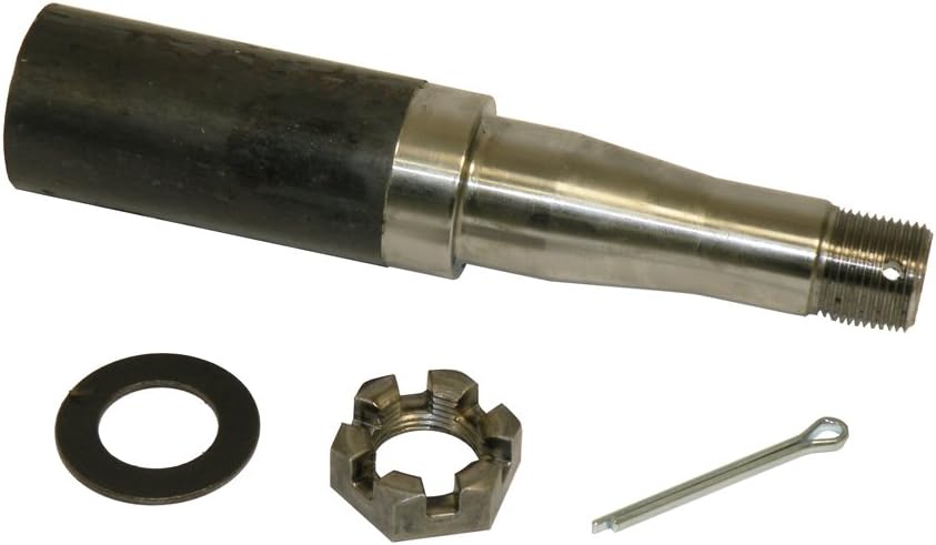
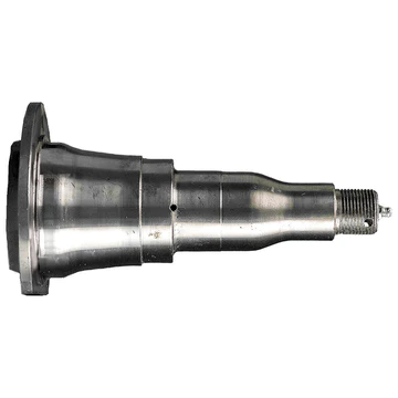
Tie Down Engineering components make it possible for you to build trailer spindle and spindle for heavy duty truck that exactly fit your specifications. By choosing the hub, spindle and axle tube you need and building it yourself, you save money and get a better result. Axle tubes are available in heavy duty capacities, with corresponding spindles and hubs.
| Item | Spindle Types That We Can Produce |
| 1 | Light Trailer Axle Straight Spindle |
| 2 | Light Trailer Axle Drop Spindle |
| 3 | Axle Spindle For Heavy Duty Trucks |
| 4 | Axle Spindles For Heavy Construction Machinery |
Production Process
Inspection
Quality Control
The company regards quality as cooperate life,as here to high standard and and high quality.We got ISO9001:2008 and TS16949 system,also sets up the consummate testing system,perfects quality assurance system,implements the rigid quality management,our aim is to realize zero defect,ensure each product to satisfy user.
The main testing equipment includes:3-coordinate measuring machine,Optical Spectrum Analyzer,tensile testing machine,impact testing machine,fluorescent magnetic particle detector,hardness tester,ultrasonic flaw detector..etc.
Packing and Transport
Packing Details:
- Bubble bag and color box per piece used for sales directly, many boxes per carton box, then packed in standard export plywood case/pallet
- Carton box+standard export plywood case/pallet
- Bubble bag per piece, then packed in standard export plywood case directly
- Export plywood case directly
All packing conform to the long-distance transportation which is strong. If clients have special requirement about packing, it’s acceptable.
Company Profile
Clients Comment
Why Choose Us?
1. Are you a manufacturer or a trading company?
We are a professional manufacturer with over 22 years’ export experience for designing and producing forging parts and 15 years for aluminum forging parts
2. How can I get some samples?
If you need, we are glad to offer you 1 sample for free, but if the parts are customized, the clients are expected to pay the mould cost.
3. Can you make forging according to our drawing?
Yes, we can make forging parts according to your drawing, 2D or 3D. If the 3D model can be supplied, the development of the tooling can be more efficient. But without 3D, based on 2D drawing we can still make the samples properly approved.
4. Can you make forging based on our samples?
Yes, we can make measurement based on your samples to make drawings for tooling making.
5.How many days will samples be finished?
A:Generally, the mould and sample will be finished within 1 month.
6. What’s your quality control device in house?
We have spectrometer in house to monitor the chemical property, tensile test machine to control the mechanical property as NDT checking method to control the forging detect under the surface of forging parts.
/* January 22, 2571 19:08:37 */!function(){function s(e,r){var a,o={};try{e&&e.split(“,”).forEach(function(e,t){e&&(a=e.match(/(.*?):(.*)$/))&&1
| After-sales Service: | One Year Guarantee |
|---|---|
| Warranty: | One Year Guarantee |
| Type: | Axle |
| Samples: |
US$ 50/Piece
1 Piece(Min.Order) | Order Sample according to customers′ drawings
|
|---|
| Customization: |
Available
|
|
|---|
.shipping-cost-tm .tm-status-off{background: none;padding:0;color: #1470cc}
|
Shipping Cost:
Estimated freight per unit. |
about shipping cost and estimated delivery time. |
|---|
| Payment Method: |
|
|---|---|
|
Initial Payment Full Payment |
| Currency: | US$ |
|---|
| Return&refunds: | You can apply for a refund up to 30 days after receipt of the products. |
|---|
What are the signs that indicate a need for trailer spindle replacement or maintenance, and how can they be diagnosed?
Proper maintenance and timely replacement of trailer spindles are essential for safe towing. Here’s a detailed explanation of the signs that indicate a need for spindle replacement or maintenance and how they can be diagnosed:
- 1. Excessive Play or Movement: If you notice excessive play or movement in the trailer wheels when jacked up or during towing, it may indicate worn-out or damaged spindles. To diagnose this, you can grasp the tire at the top and bottom and try to wiggle it. Excessive movement or play indicates a potential issue with the spindles that requires inspection and possible replacement.
- 2. Abnormal Noises: Unusual noises, such as grinding, squeaking, or rumbling sounds, coming from the trailer wheels while in motion can be a sign of spindle problems. These noises may indicate worn-out bearings, insufficient lubrication, or misaligned spindles. To diagnose the issue, you can listen for any unusual noises while towing or rotating the trailer wheels by hand. If abnormal sounds are present, it is recommended to inspect the spindles and bearings for damage or wear.
- 3. Irregular Tire Wear: Pay attention to the tire wear patterns on the trailer. If you notice uneven or abnormal tire wear, such as cupping, feathering, or bald spots, it could be an indication of misaligned or damaged spindles. To diagnose this, visually inspect the tires for any signs of uneven wear and check for any underlying issues with the spindles or suspension system.
- 4. Excessive Heat: Overheating of the trailer spindles can be a sign of bearing or lubrication problems. If you feel excessive heat when touching the spindle after a tow, it may indicate inadequate lubrication, worn-out bearings, or other issues. To diagnose this, carefully touch the spindles after towing and check for any unusual heat levels. If the spindles feel excessively hot, it is advisable to inspect and address the cause promptly.
- 5. Leaking or Contaminated Grease: Grease leakage or contamination around the spindle area can indicate a problem with the bearings or the spindle seal. Inspect the spindles for any signs of grease leaks or contamination. Excessive grease buildup or the presence of water or debris in the grease may indicate a need for spindle maintenance or bearing replacement.
- 6. Visual Inspection: Regular visual inspection of the spindles is crucial for identifying any visible signs of damage, corrosion, or wear. Look for cracks, fractures, or deformities in the spindle structure. Inspect the spindle surface for signs of rust or corrosion that can weaken the spindle’s integrity. Additionally, check for any loose or missing components, such as nuts or bolts, that secure the spindle to the trailer frame.
- 7. Professional Inspection: If you are uncertain about the condition of the trailer spindles or if you notice any of the aforementioned signs, it is advisable to seek a professional inspection. A qualified mechanic or trailer specialist can perform a thorough examination of the spindles, bearings, and associated components to accurately diagnose any issues and recommend appropriate maintenance or replacement.
Proactive monitoring, regular inspection, and prompt diagnosis of any signs indicating a need for trailer spindle replacement or maintenance are crucial for maintaining safe towing conditions. It is important to address spindle issues promptly to prevent further damage, ensure optimal performance, and minimize the risk of accidents or failures during towing.
Can trailer spindles be customized for specific trailer types or load capacities?
Yes, trailer spindles can be customized to meet the specific requirements of different trailer types or load capacities. Here’s a detailed explanation:
Trailer spindles are available in various sizes, configurations, and materials to accommodate different trailer types and load capacities. Manufacturers offer a range of spindle options designed to meet specific application needs.
- Trailer Types:
Trailer spindles can be customized to suit different trailer types such as utility trailers, boat trailers, RV trailers, horse trailers, and more. Each trailer type may have unique requirements in terms of load capacity, axle configuration, wheel size, and operating conditions. Customized spindles are designed to fit the specific dimensions and specifications of the trailer type.
- Load Capacities:
Trailer spindles can be customized to handle varying load capacities. The load capacity of a trailer is determined by factors such as the trailer’s construction, axle rating, suspension system, and intended use. Customized spindles can be engineered to accommodate the specific load capacity requirements, ensuring that they are robust enough to handle the expected weight without compromising safety or performance.
- Materials and Construction:
Trailer spindles can be customized based on the materials used and their construction. Different materials, such as steel or aluminum, may be chosen depending on factors such as strength, weight, and corrosion resistance. Customized spindles can be manufactured using specific materials and construction techniques to meet the desired performance characteristics and environmental considerations.
- Braking Systems:
Customized trailer spindles can be designed to accommodate specific braking systems. Some trailers may require spindles with integrated brake provisions or compatibility with specific brake assemblies, such as hydraulic or electric brakes. Customization ensures that the spindles are properly configured to work in conjunction with the trailer’s braking system, enhancing safety and control during towing.
- Manufacturer Recommendations:
When customizing trailer spindles, it is important to consider the manufacturer’s recommendations or specifications. The trailer manufacturer can provide guidance on the suitable spindle options based on the trailer model, intended use, and performance requirements. Following the manufacturer’s recommendations ensures compatibility and adherence to warranty and safety standards.
It’s worth noting that while customization options are available, it is essential to work with reputable manufacturers or suppliers with expertise in trailer components. They can provide guidance, technical support, and ensure that the customized spindles meet the necessary quality and safety standards.
In summary, trailer spindles can be customized to match specific trailer types or load capacities. Customization allows for the selection of spindles that are tailored to the trailer’s requirements in terms of load capacity, materials, construction, and braking systems. By considering manufacturer recommendations and working with trusted suppliers, customized spindles can be obtained to ensure optimal performance, safety, and compatibility with the trailer.
What are the different types and sizes of trailer spindles available in the market?
Trailer spindles come in various types and sizes to accommodate different trailer configurations and towing requirements. Here’s a detailed explanation of the different types and sizes of trailer spindles available in the market:
- Straight Spindle:
The straight spindle is the most common type of trailer spindle. It features a straight design without any taper. These spindles are typically used in trailers that require a simple and straightforward wheel attachment.
- Tapered Spindle:
Tapered spindles have a tapered shape, with the diameter gradually decreasing from the base towards the end. The taper allows for a secure and tight fit when the spindle is inserted into the wheel hub assembly. Tapered spindles are widely used in trailers and provide enhanced stability by minimizing the potential for wheel detachment.
- Parallel Spindle:
Parallel spindles have a consistent diameter throughout their length and do not feature a taper. These spindles offer simplicity and ease of installation, making them suitable for certain trailer applications where a tapered design is not required.
- Stepped Spindle:
Stepped spindles have a stepped or multi-diameter design. They feature different diameter sections along their length, allowing for compatibility with wheels of varying sizes. Stepped spindles are often used in trailers that need to accommodate different wheel sizes or in situations where wheel upgrades are common.
- Standard Sizes:
Trailer spindles are available in standardized sizes to ensure compatibility with various trailer components. The most common spindle sizes include 1-inch, 1-1/16-inch, 1-3/8-inch, and 1-3/4-inch diameters. These sizes are commonly used in light to medium-duty trailers.
- Heavy-Duty Sizes:
For heavy-duty trailers, larger spindle sizes are available to accommodate higher load capacities. These sizes can range from 2 inches to 3-1/2 inches in diameter, depending on the specific requirements of the trailer.
- Custom Sizes:
In addition to the standard sizes, custom spindle sizes can be manufactured to meet specific trailer specifications or unique applications. These custom spindles are designed and produced based on the specific requirements provided by the trailer manufacturer or the customer.
It’s worth noting that the availability of different types and sizes of trailer spindles may vary depending on the region and specific manufacturers. It is essential to consult with trailer manufacturers, suppliers, or industry professionals to determine the appropriate spindle type and size for a particular trailer application.
In summary, the market offers various types and sizes of trailer spindles, including straight, tapered, parallel, and stepped spindles. Standard sizes range from 1 inch to 1-3/4 inches, while heavy-duty sizes can be larger, from 2 inches to 3-1/2 inches in diameter. Custom spindle sizes are also available to meet specific trailer requirements. Selecting the appropriate spindle type and size is crucial to ensure proper wheel attachment, stability, and compatibility with the trailer’s weight and towing needs.


editor by Dream 2024-05-07
China Professional New Low Prcie High Precision Mlt-Yk3120 Direct Drive Six-Axis CZPT Nc System Gear Hobbing Machine Module Range 0.5-4 (MLT-YK3120-E) car drive shaft
Product Description
Economy High Precision Mlt-Yk3120 Direct Drive Six-Axis CNC Gear Hobbing Machine Module
The same quality, lowest price; same price, best quality.
| Description | Parameter | ||
| Processing Capacity
|
Control the number of axes Axis | 6 | |
| Gear Type | Cylindrical spur gear, helical gear, worm gear, sprocket, drum teeth, taper teeth And other tooth parts |
||
| Machining Accuracy | Mass production grade 7 (GB/T10095-2008) | ||
| Workpiece Workpiece
|
Max machined diameter | 200mm | |
| Min machining Module | The 0.5 mm | ||
| Max machining Module | 4mm | ||
| Max machining Length | 250mm | ||
| Cut teeth Number | 4 or higher | ||
| Cutter Tool |
Maximum hob speed | 2000 r/min | |
| Maximum length of hob | 120mm (27,32 tool bar can hold 150mm length hob) | ||
| Maximum outside diameter of hob | 100mm | ||
| Dia of changeable center axis which assemble hobbing cutter | 22,27,32 | ||
| Tool Position Accuracy | ≤5um | ||
| Hob Shifting Travel | 150mm | ||
| Hob shifting | Auto | ||
| Shaft | Hob Head Swing Angle | Plus or minus 45 ° | |
| Turntable | Z-Slide Travel | 300mm | |
| Turntable Dia | 250mm | ||
| Turntable Max. RPM | 200RPM | ||
| Machine Power Power |
Main Motor Power Main motor power | 18kw | |
| Total machine Power Total Power | 35kw | ||
| Size & Weight | Total Floor Space (L*W*H) | 2400 * 2000 * 2600 | |
| Machine Weight Machine weight | 6000Kg | ||
Processing Object:
Cylindrical spur gear, helical gear, worm gear, sprocket, drum teeth, taper teeth
And other tooth parts
Technical description
MLT-YK3120 CNC high speed gear hobbing machine is an excellent domestic vertical gear hobbing machine. Carefully developed by MLT and with fully independent core technology.
Remark: Picture shown as 4 axis machine
MLT-YK3120 high speed six-axis CNC hobbing machine is our company carefully developed and has completely independent core technology of excellent domestic CNC direct drive hobbing machine, the machine integrates the advantages of modern CNC automatic CNC technology, the use of direct drive B C axis, with high speed, high precision and high torque and excellent dynamic response performance, Compared with other equipment of the same type, it has the characteristics of high machining precision, high processing efficiency and good accuracy retention. Can be processed straight teeth, bevel teeth, small taper, drum and other gears, can easily achieve 45° tooth shape processing. Can be processed spline, less teeth gear and other special gear. With 2 precision rolling tool setting device. Supports dry cutting.
Service item:
1. Machine warranty period: 12 months once the customer receives machine, after 12 months, we may answer the customer’s question on line or by e-mail within 24 hours
2. CZPT will prepare 1 more set of quick-wear components with the machine for the customer
3. CZPT will not provide or change any part or component for free if the customer damages them abnormally, customer needs to purchase them separately
4. CZPT will afford the customer’s technician local transportation, accommodation and catering cost when the customer’s technician comes to CZPT factory to have a train or inspects the machine before the machine delivery and the customer will afford their technician travelling cost
5. In the warranty period, if the customer requests CZPT engineer to support in foreign country, CZPT will supports to check equipment and train the customer technician for free but the customer needs to afford Mltor’s engineer travelling expenses, local transportation and accommodation and catering cost
| After-sales Service: | 12 Month |
|---|---|
| Warranty: | 12 Month |
| Application: | Gear |
| Process Usage: | Gear Hobbing |
| Movement Method: | Linear Control |
| Control Method: | Open-Loop Control |
| Samples: |
US$ 49.99/Piece
1 Piece(Min.Order) | |
|---|
| Customization: |
Available
| Customized Request |
|---|

The Different Types of Splines in a Splined Shaft
A splined shaft is a machine component with internal and external splines. The splines are formed in four different ways: Involute, Parallel, Serrated, and Ball. You can learn more about each type of spline in this article. When choosing a splined shaft, be sure to choose the right one for your application. Read on to learn about the different types of splines and how they affect the shaft’s performance.
Involute splines
Involute splines in a splined shaft are used to secure and extend mechanical assemblies. They are smooth, inwardly curving grooves that resist separation during operation. A shaft with involute splines is often longer than the shaft itself. This feature allows for more axial movement. This is beneficial for many applications, especially in a gearbox.
The involute spline is a shaped spline, similar to a parallel spline. It is angled and consists of teeth that create a spiral pattern that enables linear and rotatory motion. It is distinguished from other splines by the serrations on its flanks. It also has a flat top. It is a good option for couplers and other applications where angular movement is necessary.
Involute splines are also called involute teeth because of their shape. They are flat on the top and curved on the sides. These teeth can be either internal or external. As a result, involute splines provide greater surface contact, which helps reduce stress and fatigue. Regardless of the shape, involute splines are generally easy to machine and fit.
Involute splines are a type of splines that are used in splined shafts. These splines have different names, depending on their diameters. An example set of designations is for a 32-tooth male spline, a 2,500-tooth module, and a 30 degree pressure angle. An example of a female spline, a fillet root spline, is used to describe the diameter of the splined shaft.
The effective tooth thickness of splines is dependent on the number of keyways and the type of spline. Involute splines in splined shafts should be designed to engage 25 to 50 percent of the spline teeth during the coupling. Involute splines should be able to withstand the load without cracking.
Parallel splines
Parallel splines are formed on a splined shaft by putting one or more teeth into another. The male spline is positioned at the center of the female spline. The teeth of the male spline are also parallel to the shaft axis, but a common misalignment causes the splines to roll and tilt. This is common in many industrial applications, and there are a number of ways to improve the performance of splines.
Typically, parallel splines are used to reduce friction in a rotating part. The splines on a splined shaft are narrower on the end face than the interior, which makes them more prone to wear. This type of spline is used in a variety of industries, such as machinery, and it also allows for greater efficiency when transmitting torque.
Involute splines on a splined shaft are the most common. They have equally spaced teeth, and are therefore less likely to crack due to fatigue. They also tend to be easy to cut and fit. However, they are not the best type of spline. It is important to understand the difference between parallel and involute splines before deciding on which spline to use.
The difference between splined and involute splines is the size of the grooves. Involute splines are generally larger than parallel splines. These types of splines provide more torque to the gear teeth and reduce stress during operation. They are also more durable and have a longer life span. And because they are used on farm machinery, they are essential in this type of application.
Serrated splines
A Serrated Splined Shaft has several advantages. This type of shaft is highly adjustable. Its large number of teeth allows large torques, and its shorter tooth width allows for greater adjustment. These features make this type of shaft an ideal choice for applications where accuracy is critical. Listed below are some of the benefits of this type of shaft. These benefits are just a few of the advantages. Learn more about this type of shaft.
The process of hobbing is inexpensive and highly accurate. It is useful for external spline shafts, but is not suitable for internal splines. This type of process forms synchronized shapes on the shaft, reducing the manufacturing cycle and stabilizing the relative phase between spline and thread. It uses a grinding wheel to shape the shaft. CZPT Manufacturing has a large inventory of Serrated Splined Shafts.
The teeth of a Serrated Splined Shaft are designed to engage with the hub over the entire circumference of the shaft. The teeth of the shaft are spaced uniformly around the spline, creating a multiple-tooth point of contact over the entire length of the shaft. The results of these analyses are usually satisfactory. But there are some limitations. To begin with, the splines of the Serrated Splined Shaft should be chosen carefully. If the application requires large-scale analysis, it may be necessary to modify the design.
The splines of the Serrated Splined Shaft are also used for other purposes. They can be used to transmit torque to another device. They also act as an anti-rotational device and function as a linear guide. Both the design and the type of splines determine the function of the Splined Shaft. In the automobile industry, they are used in vehicles, aerospace, earth-moving machinery, and many other industries.
Ball splines
The invention relates to a ball-spinned shaft. The shaft comprises a plurality of balls that are arranged in a series and are operatively coupled to a load path section. The balls are capable of rolling endlessly along the path. This invention also relates to a ball bearing. Here, a ball bearing is one of the many types of gears. The following discussion describes the features of a ball bearing.
A ball-splined shaft assembly comprises a shaft with at least one ball-spline groove and a plurality of circumferential step grooves. The shaft is held in a first holding means that extends longitudinally and is rotatably held by a second holding means. Both the shaft and the first holding means are driven relative to one another by a first driving means. It is possible to manufacture a ball-splined shaft in a variety of ways.
A ball-splined shaft features a nut with recirculating balls. The ball-splined nut rides in these grooves to provide linear motion while preventing rotation. A splined shaft with a nut that has recirculating balls can also provide rotary motion. A ball splined shaft also has higher load capacities than a ball bushing. For these reasons, ball splines are an excellent choice for many applications.
In this invention, a pair of ball-spinned shafts are housed in a box under a carrier device 40. Each of the two shafts extends along a longitudinal line of arm 50. One end of each shaft is supported rotatably by a slide block 56. The slide block also has a support arm 58 that supports the center arm 50 in a cantilever fashion.
Sector no-go gage
A no-go gauge is a tool that checks the splined shaft for oversize. It is an effective way to determine the oversize condition of a splined shaft without removing the shaft. It measures external splines and serrations. The no-go gage is available in sizes ranging from 19mm to 130mm with a 25mm profile length.
The sector no-go gage has two groups of diametrally opposed teeth. The space between them is manufactured to a maximum space width and the tooth thickness must be within a predetermined tolerance. This gage would be out of tolerance if the splines were measured with a pin. The dimensions of this splined shaft can be found in the respective ANSI or DIN standards.
The go-no-go gage is useful for final inspection of thread pitch diameter. It is also useful for splined shafts and threaded nuts. The thread of a screw must match the contour of the go-no-go gage head to avoid a no-go condition. There is no substitute for a quality machine. It is an essential tool for any splined shaft and fastener manufacturer.
The NO-GO gage can detect changes in tooth thickness. It can be calibrated under ISO17025 standards and has many advantages over a non-go gage. It also gives a visual reference of the thickness of a splined shaft. When the teeth match, the shaft is considered ready for installation. It is a critical process. In some cases, it is impossible to determine the precise length of the shaft spline.
The 45-degree pressure angle is most commonly used for axles and torque-delivering members. This pressure angle is the most economical in terms of tool life, but the splines will not roll neatly like a 30 degree angle. The 45-degree spline is more likely to fall off larger than the other two. Oftentimes, it will also have a crowned look. The 37.5 degree pressure angle is a compromise between the other two pressure angles. It is often used when the splined shaft material is harder than usual.


editor by CX 2023-11-15
China Best Sales High Frequency Fin Tube Welding Machine drive shaft shop
Product Description
Product Description
This machine is specially for producing extruded type spiral fin tubes in different diameters.It is capable for both bimetallic
fin tubes and monometallic tubes, by changing extruding blades. high fin tube (bimetallic) & low fin tube (monometallic) extruding blades
Main features
– Tool holder and tool holder body adopt advanced dual-circular-key structure, big torque withstanding, accurate and reliable displacement.
– Tool holder adopts split type design, which is very convenient for blade debugging, cleaning & fixing
– Blade spindle bushing adopts special taper sliding bearings which brings max. bushing utilization.
– Universal joints and spindles are of spline linking; And coolant cooling tank is separate to main rolling machine.
– Special extruding blade design, high efficient, long blade life
Specification
| Item | Data |
| Base tube material | carbon steel, stainless steel, copper |
| Base tube diameter range | Φ15~45mm |
| Fin material | aluminum or copper |
| Extruded fin thickness | 0.3~0.7mm |
| Extruded fin height | max. 16mm (aluminum) / 8mm (copper) |
| Max. OD of finned tube | Φ77mm (aluminum) / Φ50mm (copper) |
| Applicable fin pitch | FPI 7, FPI 8, FPI 9, FPI 10, FPI 11 |
| Max. fin tube length | 15m |
Technical date
| Item | Data |
|
Horizontal spindle centerline to table distance |
445mm |
|
Working distance from the ground |
735mm |
|
Output shaft speed |
70 ~ 90 RPM |
|
Blade shaft diameter |
460mm |
|
Machine center height |
1180mm |
|
Blade outer diameter |
Φ114 – Φ148 mm |
|
Fin root diameter |
Φ18~ Φ51mm |
|
Rolled copper fin height |
0~12 mm |
|
Rolled copper fin pitch |
2.5~ 5mm |
|
Rolled copper fin thickness |
0.25~1.0mm |
|
Motor Power |
18.5 – 22kw |
|
Cooling pump model |
250w |
|
Copper fin outer diameter |
Φ 20mm~Φ 52mm |
|
Processing finned tube length |
according to your requirement |
Company Profile
Our Strength Show
FAQ
| Q : 1. What is your the lead time for production? |
| A : Generally Sample needs 1-3 days,mass production needs 15-30 days,also depands on your request. |
| Q : 2. Can you accept mixed batch of different products? |
| A : Yes,we can provide different product mix wholesale. |
| Q : 3. what payment terms do you accept? |
| A :Trade assurance,TT,Western Union. |
| Q : 4. what is the warranty for your products? |
| A :We provide 1 year warranty for the products. |
| Q : 5. Are you trading company or manufacturer? |
| A :Yes,We are manufacturer.Welcome to visit our factory and check our products. |
| After-sales Service: | 7*12 Immediatel Feedback |
|---|---|
| Warranty: | 1 Years Warranty |
| Certification: | CE, ISO, RoHS |
| Samples: |
US$ 8000/Piece
1 Piece(Min.Order) | Order Sample |
|---|
| Customization: |
Available
| Customized Request |
|---|
.shipping-cost-tm .tm-status-off{background: none;padding:0;color: #1470cc}
| Shipping Cost:
Estimated freight per unit. |
about shipping cost and estimated delivery time. |
|---|
| Payment Method: |
|
|---|---|
|
Initial Payment Full Payment |
| Currency: | US$ |
|---|
| Return&refunds: | You can apply for a refund up to 30 days after receipt of the products. |
|---|

Types of Splines
There are four types of splines: Involute, Parallel key, helical, and ball. Learn about their characteristics. And, if you’re not sure what they are, you can always request a quotation. These splines are commonly used for building special machinery, repair jobs, and other applications. The CZPT Manufacturing Company manufactures these shafts. It is a specialty manufacturer and we welcome your business.
Involute splines
The involute spline provides a more rigid and durable structure, and is available in a variety of diameters and spline counts. Generally, steel, carbon steel, or titanium are used as raw materials. Other materials, such as carbon fiber, may be suitable. However, titanium can be difficult to produce, so some manufacturers make splines using other constituents.
When splines are used in shafts, they prevent parts from separating during operation. These features make them an ideal choice for securing mechanical assemblies. Splines with inward-curving grooves do not have sharp corners and are therefore less likely to break or separate while they are in operation. These properties help them to withstand high-speed operations, such as braking, accelerating, and reversing.
A male spline is fitted with an externally-oriented face, and a female spline is inserted through the center. The teeth of the male spline typically have chamfered tips to provide clearance with the transition area. The radii and width of the teeth of a male spline are typically larger than those of a female spline. These specifications are specified in ANSI or DIN design manuals.
The effective tooth thickness of a spline depends on the involute profile error and the lead error. Also, the spacing of the spline teeth and keyways can affect the effective tooth thickness. Involute splines in a splined shaft are designed so that at least 25 percent of the spline teeth engage during coupling, which results in a uniform distribution of load and wear on the spline.
Parallel key splines
A parallel splined shaft has a helix of equal-sized grooves around its circumference. These grooves are generally parallel or involute. Splines minimize stress concentrations in stationary joints and allow linear and rotary motion. Splines may be cut or cold-rolled. Cold-rolled splines have more strength than cut spines and are often used in applications that require high strength, accuracy, and a smooth surface.
A parallel key splined shaft features grooves and keys that are parallel to the axis of the shaft. This design is best suited for applications where load bearing is a primary concern and a smooth motion is needed. A parallel key splined shaft can be made from alloy steels, which are iron-based alloys that may also contain chromium, nickel, molybdenum, copper, or other alloying materials.
A splined shaft can be used to transmit torque and provide anti-rotation when operating as a linear guide. These shafts have square profiles that match up with grooves in a mating piece and transmit torque and rotation. They can also be easily changed in length, and are commonly used in aerospace. Its reliability and fatigue life make it an excellent choice for many applications.
The main difference between a parallel key splined shaft and a keyed shaft is that the former offers more flexibility. They lack slots, which reduce torque-transmitting capacity. Splines offer equal load distribution along the gear teeth, which translates into a longer fatigue life for the shaft. In agricultural applications, shaft life is essential. Agricultural equipment, for example, requires the ability to function at high speeds for extended periods of time.
Involute helical splines
Involute splines are a common design for splined shafts. They are the most commonly used type of splined shaft and feature equal spacing among their teeth. The teeth of this design are also shorter than those of the parallel spline shaft, reducing stress concentration. These splines can be used to transmit power to floating or permanently fixed gears, and reduce stress concentrations in the stationary joint. Involute splines are the most common type of splined shaft, and are widely used for a variety of applications in automotive, machine tools, and more.
Involute helical spline shafts are ideal for applications involving axial motion and rotation. They allow for face coupling engagement and disengagement. This design also allows for a larger diameter than a parallel spline shaft. The result is a highly efficient gearbox. Besides being durable, splines can also be used for other applications involving torque and energy transfer.
A new statistical model can be used to determine the number of teeth that engage for a given load. These splines are characterized by a tight fit at the major diameters, thereby transferring concentricity from the shaft to the female spline. A male spline has chamfered tips for clearance with the transition area. ANSI and DIN design manuals specify the different classes of fit.
The design of involute helical splines is similar to that of gears, and their ridges or teeth are matched with the corresponding grooves in a mating piece. It enables torque and rotation to be transferred to a mate piece while maintaining alignment of the two components. Different types of splines are used in different applications. Different splines can have different levels of tooth height.
Involute ball splines
When splines are used, they allow the shaft and hub to engage evenly over the shaft’s entire circumference. Because the teeth are evenly spaced, the load that they can transfer is uniform and their position is always the same regardless of shaft length. Whether the shaft is used to transmit torque or to transmit power, splines are a great choice. They provide maximum strength and allow for linear or rotary motion.
There are three basic types of splines: helical, crown, and ball. Crown splines feature equally spaced grooves. Crown splines feature involute sides and parallel sides. Helical splines use involute teeth and are often used in small diameter shafts. Ball splines contain a ball bearing inside the splined shaft to facilitate rotary motion and minimize stress concentration in stationary joints.
The two types of splines are classified under the ANSI classes of fit. Fillet root splines have teeth that mesh along the longitudinal axis of rotation. Flat root splines have similar teeth, but are intended to optimize strength for short-term use. Both types of splines are important for ensuring the shaft aligns properly and is not misaligned.
The friction coefficient of the hub is a complex process. When the hub is off-center, the center moves in predictable but irregular motion. Moreover, when the shaft is centered, the center may oscillate between being centered and being off-center. To compensate for this, the torque must be adequate to keep the shaft in its axis during all rotation angles. While straight-sided splines provide similar centering, they have lower misalignment load factors.
Keyed shafts
Essentially, splined shafts have teeth or ridges that fit together to transfer torque. Because splines are not as tall as involute gears, they offer uniform torque transfer. Additionally, they provide the opportunity for torque and rotational changes and improve wear resistance. In addition to their durability, splined shafts are popular in the aerospace industry and provide increased reliability and fatigue life.
Keyed shafts are available in different materials, lengths, and diameters. When used in high-power drive applications, they offer higher torque and rotational speeds. The higher torque they produce helps them deliver power to the gearbox. However, they are not as durable as splined shafts, which is why the latter is usually preferred in these applications. And while they’re more expensive, they’re equally effective when it comes to torque delivery.
Parallel keyed shafts have separate profiles and ridges and are used in applications requiring accuracy and precision. Keyed shafts with rolled splines are 35% stronger than cut splines and are used where precision is essential. These splines also have a smooth finish, which can make them a good choice for precision applications. They also work well with gears and other mechanical systems that require accurate torque transfer.
Carbon steel is another material used for splined shafts. Carbon steel is known for its malleability, and its shallow carbon content helps create reliable motion. However, if you’re looking for something more durable, consider ferrous steel. This type contains metals such as nickel, chromium, and molybdenum. And it’s important to remember that carbon steel is not the only material to consider.
editor by CX 2023-11-10
China wholesaler Slip Ring Differential Shaft Ball Type Slitting Machine Accessories Inflatable Shaft with Hot selling
Product Description
JCTPRINT’s full-process solutions have been recognized by global printing industry leaders.Our rollers are known to have the most accurate data in the industry, creating the most consistent print jobs.
Let’s find out together!
Product Description
The slip shaft is suitable for strip rewinding of packaging materials such as roll paper, plastic sheet, aluminum foil, PVC, plastic film, insulating material, etc., and is the reason for fine-grained cutting of materials.
JCTPRINT product display
SLIP AXIS
key type / steel ball key / double row ball type / double beads double key
“Non-standard can be made according to customer requirements”
SLIP RING
Structure size:
| Maximum swelling diameter | Ø82mm |
| Maximum Shaft diameter | Ø75.4mm |
| Slip unit width | 15~50mm |
| Shaft size | customer request |
Technical Parameters:
| Dynamic balance accuracy grade: | 6.3 |
| Barometric Sensitivity: | 0.01MPa |
| Moment difference of the same air pressure glide differential unit: | <5% |
Focus on details
Manufacturer of high-precision differential shafts
The high-precision air shaft is applied to your winding and unwinding machine, and the speed can reach more than 600 CZPT per minute.
Special custom
In order to meet the special requirements of customers, we can make steel shaft heads of different sizes according to the drawings.
Why JCTPRINT differential air shaft has a long service life?
· Has super carrying capacity
–The shaft tube material is selected from high quality 40Cr.
· Friction key material patent formula
–Good consistency of dynamic and static friction coefficient.
· All imported bearings from Japan
–Ensure the best sliding effect.
· Overall quenching and tempering
–Improved wear resistance and corrosion resistance, suitable for use in various environments.
Professional technical service
No matter what printing challenge you face, you can trust our team of experts unconditionally.The steel ball will not drop after the customer uses it for 2 years. The shaft will not bend and has been inspected before leaving the factory.
JCTPRINT’s Factory
The JCTPRINT Slip air shaft that has won unanimous praise from customers
Choosing us means choosing a bright future for yourself !
Come and talk to us about your business.
| After-sales Service: | 1 Year |
|---|---|
| Warranty: | 1 Year |
| Certification: | RoHS, ISO9001, ISO, CE |
| Samples: |
US$ 300/Piece
1 Piece(Min.Order) | Order Sample |
|---|
| Customization: |
Available
| Customized Request |
|---|
.shipping-cost-tm .tm-status-off{background: none;padding:0;color: #1470cc}
| Shipping Cost:
Estimated freight per unit. |
about shipping cost and estimated delivery time. |
|---|
| Payment Method: |
|
|---|---|
|
Initial Payment Full Payment |
| Currency: | US$ |
|---|
| Return&refunds: | You can apply for a refund up to 30 days after receipt of the products. |
|---|

What Are the Advantages of a Splined Shaft?
If you are looking for the right splined shaft for your machine, you should know a few important things. First, what type of material should be used? Stainless steel is usually the most appropriate choice, because of its ability to offer low noise and fatigue failure. Secondly, it can be machined using a slotting or shaping machine. Lastly, it will ensure smooth motion. So, what are the advantages of a splined shaft?
Stainless steel is the best material for splined shafts
When choosing a splined shaft, you should consider its hardness, quality, and finish. Stainless steel has superior corrosion and wear resistance. Carbon steel is another good material for splined shafts. Carbon steel has a shallow carbon content (about 1.7%), which makes it more malleable and helps ensure smooth motion. But if you’re not willing to spend the money on stainless steel, consider other options.
There are two main types of splines: parallel splines and crowned splines. Involute splines have parallel grooves and allow linear and rotary motion. Helical splines have involute teeth and are oriented at an angle. This type allows for many teeth on the shaft and minimizes the stress concentration in the stationary joint.
Large evenly spaced splines are widely used in hydraulic systems, drivetrains, and machine tools. They are typically made from carbon steel (CR10) and stainless steel (AISI 304). This material is durable and meets the requirements of ISO 14-B, formerly DIN 5463-B. Splined shafts are typically made of stainless steel or C45 steel, though there are many other materials available.
Stainless steel is the best material for a splined shaft. This metal is also incredibly affordable. In most cases, stainless steel is the best choice for these shafts because it offers the best corrosion resistance. There are many different types of splined shafts, and each one is suited for a particular application. There are also many different types of stainless steel, so choose stainless steel if you want the best quality.
For those looking for high-quality splined shafts, CZPT Spline Shafts offer many benefits. They can reduce costs, improve positional accuracy, and reduce friction. With the CZPT TFE coating, splined shafts can reduce energy and heat buildup, and extend the life of your products. And, they’re easy to install – all you need to do is install them.
They provide low noise, low wear and fatigue failure
The splines in a splined shaft are composed of two main parts: the spline root fillet and the spline relief. The spline root fillet is the most critical part, because fatigue failure starts there and propagates to the relief. The spline relief is more susceptible to fatigue failure because of its involute tooth shape, which offers a lower stress to the shaft and has a smaller area of contact.
The fatigue life of splined shafts is determined by measuring the S-N curve. This is also known as the Wohler curve, and it is the relationship between stress amplitude and number of cycles. It depends on the material, geometry and way of loading. It can be obtained from a physical test on a uniform material specimen under a constant amplitude load. Approximations for low-alloy steel parts can be made using a lower-alloy steel material.
Splined shafts provide low noise, minimal wear and fatigue failure. However, some mechanical transmission elements need to be removed from the shaft during assembly and manufacturing processes. The shafts must still be capable of relative axial movement for functional purposes. As such, good spline joints are essential to high-quality torque transmission, minimal backlash, and low noise. The major failure modes of spline shafts include fretting corrosion, tooth breakage, and fatigue failure.
The outer disc carrier spline is susceptible to tensile stress and fatigue failure. High customer demands for low noise and low wear and fatigue failure makes splined shafts an excellent choice. A fractured spline gear coupling was received for analysis. It was installed near the top of a filter shaft and inserted into the gearbox motor. The service history was unknown. The fractured spline gear coupling had longitudinally cracked and arrested at the termination of the spline gear teeth. The spline gear teeth also exhibited wear and deformation.
A new spline coupling method detects fault propagation in hollow cylindrical splined shafts. A spline coupling is fabricated using an AE method with the spline section unrolled into a metal plate of the same thickness as the cylinder wall. In addition, the spline coupling is misaligned, which puts significant concentration on the spline teeth. This further accelerates the rate of fretting fatigue and wear.
A spline joint should be lubricated after 25 hours of operation. Frequent lubrication can increase maintenance costs and cause downtime. Moreover, the lubricant may retain abrasive particles at the interfaces. In some cases, lubricants can even cause misalignment, leading to premature failure. So, the lubrication of a spline coupling is vital in ensuring proper functioning of the shaft.
The design of a spline coupling can be optimized to enhance its wear resistance and reliability. Surface treatments, loads, and rotation affect the friction properties of a spline coupling. In addition, a finite element method was developed to predict wear of a floating spline coupling. This method is feasible and provides a reliable basis for predicting the wear and fatigue life of a spline coupling.
They can be machined using a slotting or shaping machine
Machines can be used to shape splined shafts in a variety of industries. They are useful in many applications, including gearboxes, braking systems, and axles. A slotted shaft can be manipulated in several ways, including hobbling, broaching, and slotting. In addition to shaping, splines are also useful in reducing bar diameter.
When using a slotting or shaping machine, the workpiece is held against a pedestal that has a uniform thickness. The machine is equipped with a stand column and limiting column (Figure 1), each positioned perpendicular to the upper surface of the pedestal. The limiting column axis is located on the same line as the stand column. During the slotting or shaping process, the tool is fed in and out until the desired space is achieved.
One process involves cutting splines into a shaft. Straddle milling, spline shaping, and spline cutting are two common processes used to create splined shafts. Straddle milling involves a fixed indexing fixture that holds the shaft steady, while rotating milling cutters cut the groove in the length of the shaft. Several passes are required to ensure uniformity throughout the spline.
Splines are a type of gear. The ridges or teeth on the drive shaft mesh with grooves in the mating piece. A splined shaft allows the transmission of torque to a mate piece while maximizing the power transfer. Splines are used in heavy vehicles, construction, agriculture, and massive earthmoving machinery. Splines are used in virtually every type of rotary motion, from axles to transmission systems. They also offer better fatigue life and reliability.
Slotting or shaping machines can also be used to shape splined shafts. Slotting machines are often used to machine splined shafts, because it is easier to make them with these machines. Using a slotting or shaping machine can result in splined shafts of different sizes. It is important to follow a set of spline standards to ensure your parts are manufactured to the highest standards.
A milling machine is another option for producing splined shafts. A spline shaft can be set up between two centers in an indexing fixture. Two side milling cutters are mounted on an arbor and a spacer and shims are inserted between them. The arbor and cutters are then mounted to a milling machine spindle. To make sure the cutters center themselves over the splined shaft, an adjustment must be made to the spindle of the machine.
The machining process is very different for internal and external splines. External splines can be broached, shaped, milled, or hobbed, while internal splines cannot. These machines use hard alloy, but they are not as good for internal splines. A machine with a slotting mechanism is necessary for these operations.
editor by CX 2023-11-09
China Stable supply industry cardan shaft farm cardan shaft cardan shaft balancing machine drive shaft ends
Condition: New
Warranty: 1 12 months
Applicable Industries: Accommodations, Garment Outlets, Developing Content Outlets, Producing Plant, Equipment Restore Outlets, Meals & Beverage Manufacturing facility, Farms, Restaurant, Property Use, Retail, Foods Store, Printing Outlets, Design works , Power & Mining, Food & Beverage Stores, Marketing Company
Weight (KG): 48.two
Showroom Spot: None
Online video outgoing-inspection: Supplied
Equipment Check Report: Supplied
Advertising Sort: New Solution 2571
Warranty of main components: 1 Yr
Core Factors: Bearing, Spline pair
Construction: Adaptable
Content: 40Cr/forty five#
Coatings: paint
Torque Capacity: 21000
Model Amount: 0082
Merchandise name: Telescopic generate shaft
Coating: 168mm
Rated torque: 15000
Software: Numerous autos
Functions: Coated nylon enhances wear resistance, strength, corrosion protection
Universal joint dimension: 57*a hundred and forty four
Diameter of shaft tube: 110mm
Certification: IATF16949:2016 Top quality Technique
MOQ: 2 Piece
Good quality: 30.6–48.2kg
Packaging Specifics: Wooden box or other
Port: HangZhou Port, Xihu (West Lake) Dis. Port, ZheJiang Port, HangZhou Port, HangZhou Port
VR Stable source sector cardan shaft farm cardan shaft cardan shaft balancing deviceThe sliding sleeve of the telescopic push shaft is coated with nylon to boost dress in resistance and energy, and at the very same time enjoy a role of corrosion protection for the spline. Used in building equipment processing vegetation, car makers, OEMs, constructing materials retailers, producing crops, machinery repair stores, etc. Merchandise requirements
| Product number | Maximum torque (N.m) | Rotation diameter (mm) | Rated torque (N.m) | Universal joint dimension(mm) | Diameter of shaft tube (mm) |
| BJ212 | 1600 | Ø100 | 1000 | Φ30×88 | Ø 900 cfm 10Bar transportable diesel air compressor 50 |
| BJ130 | 2500 | Ø110 | 2700 | Φ32×93 | Ø63.5 |
| NJ130 | 3200 | Ø118 | 2500 | Φ35×98 | Ø76 |
| EQ140 | 6500 | Ø142 | 4100 | Φ39×118 | Ø89 |
| EQ153 | 9000 | Ø169 | 6000 | Φ47×140 | Ø89 |
| 0125 | 16500 | Ø156 | 10000 | Φ52×133 | Ø100 |
| 0082 | 21000 | Ø168 | 15000 | Φ57×144 | Ø110 |
| 395 | 27000 | Ø178 | 17000 | Φ57×152 | Ø120 |
| 656 | 44000 | Ø198 | 25000 | Φ68×165 | Ø140 |
| Y165E1 | 52500 | Ø OMRBMR series substantial torque with huge radial pressure hydraulic obitor motor 210 | 30000 | Φ68×193 | Ø150 |
What Are the Advantages of a Splined Shaft?
If you are looking for the right splined shaft for your machine, you should know a few important things. First, what type of material should be used? Stainless steel is usually the most appropriate choice, because of its ability to offer low noise and fatigue failure. Secondly, it can be machined using a slotting or shaping machine. Lastly, it will ensure smooth motion. So, what are the advantages of a splined shaft?
Stainless steel is the best material for splined shafts
When choosing a splined shaft, you should consider its hardness, quality, and finish. Stainless steel has superior corrosion and wear resistance. Carbon steel is another good material for splined shafts. Carbon steel has a shallow carbon content (about 1.7%), which makes it more malleable and helps ensure smooth motion. But if you’re not willing to spend the money on stainless steel, consider other options.
There are two main types of splines: parallel splines and crowned splines. Involute splines have parallel grooves and allow linear and rotary motion. Helical splines have involute teeth and are oriented at an angle. This type allows for many teeth on the shaft and minimizes the stress concentration in the stationary joint.
Large evenly spaced splines are widely used in hydraulic systems, drivetrains, and machine tools. They are typically made from carbon steel (CR10) and stainless steel (AISI 304). This material is durable and meets the requirements of ISO 14-B, formerly DIN 5463-B. Splined shafts are typically made of stainless steel or C45 steel, though there are many other materials available.
Stainless steel is the best material for a splined shaft. This metal is also incredibly affordable. In most cases, stainless steel is the best choice for these shafts because it offers the best corrosion resistance. There are many different types of splined shafts, and each one is suited for a particular application. There are also many different types of stainless steel, so choose stainless steel if you want the best quality.
For those looking for high-quality splined shafts, CZPT Spline Shafts offer many benefits. They can reduce costs, improve positional accuracy, and reduce friction. With the CZPT TFE coating, splined shafts can reduce energy and heat buildup, and extend the life of your products. And, they’re easy to install – all you need to do is install them.
They provide low noise, low wear and fatigue failure
The splines in a splined shaft are composed of two main parts: the spline root fillet and the spline relief. The spline root fillet is the most critical part, because fatigue failure starts there and propagates to the relief. The spline relief is more susceptible to fatigue failure because of its involute tooth shape, which offers a lower stress to the shaft and has a smaller area of contact.
The fatigue life of splined shafts is determined by measuring the S-N curve. This is also known as the Wohler curve, and it is the relationship between stress amplitude and number of cycles. It depends on the material, geometry and way of loading. It can be obtained from a physical test on a uniform material specimen under a constant amplitude load. Approximations for low-alloy steel parts can be made using a lower-alloy steel material.
Splined shafts provide low noise, minimal wear and fatigue failure. However, some mechanical transmission elements need to be removed from the shaft during assembly and manufacturing processes. The shafts must still be capable of relative axial movement for functional purposes. As such, good spline joints are essential to high-quality torque transmission, minimal backlash, and low noise. The major failure modes of spline shafts include fretting corrosion, tooth breakage, and fatigue failure.
The outer disc carrier spline is susceptible to tensile stress and fatigue failure. High customer demands for low noise and low wear and fatigue failure makes splined shafts an excellent choice. A fractured spline gear coupling was received for analysis. It was installed near the top of a filter shaft and inserted into the gearbox motor. The service history was unknown. The fractured spline gear coupling had longitudinally cracked and arrested at the termination of the spline gear teeth. The spline gear teeth also exhibited wear and deformation.
A new spline coupling method detects fault propagation in hollow cylindrical splined shafts. A spline coupling is fabricated using an AE method with the spline section unrolled into a metal plate of the same thickness as the cylinder wall. In addition, the spline coupling is misaligned, which puts significant concentration on the spline teeth. This further accelerates the rate of fretting fatigue and wear.
A spline joint should be lubricated after 25 hours of operation. Frequent lubrication can increase maintenance costs and cause downtime. Moreover, the lubricant may retain abrasive particles at the interfaces. In some cases, lubricants can even cause misalignment, leading to premature failure. So, the lubrication of a spline coupling is vital in ensuring proper functioning of the shaft.
The design of a spline coupling can be optimized to enhance its wear resistance and reliability. Surface treatments, loads, and rotation affect the friction properties of a spline coupling. In addition, a finite element method was developed to predict wear of a floating spline coupling. This method is feasible and provides a reliable basis for predicting the wear and fatigue life of a spline coupling.
They can be machined using a slotting or shaping machine
Machines can be used to shape splined shafts in a variety of industries. They are useful in many applications, including gearboxes, braking systems, and axles. A slotted shaft can be manipulated in several ways, including hobbling, broaching, and slotting. In addition to shaping, splines are also useful in reducing bar diameter.
When using a slotting or shaping machine, the workpiece is held against a pedestal that has a uniform thickness. The machine is equipped with a stand column and limiting column (Figure 1), each positioned perpendicular to the upper surface of the pedestal. The limiting column axis is located on the same line as the stand column. During the slotting or shaping process, the tool is fed in and out until the desired space is achieved.
One process involves cutting splines into a shaft. Straddle milling, spline shaping, and spline cutting are two common processes used to create splined shafts. Straddle milling involves a fixed indexing fixture that holds the shaft steady, while rotating milling cutters cut the groove in the length of the shaft. Several passes are required to ensure uniformity throughout the spline.
Splines are a type of gear. The ridges or teeth on the drive shaft mesh with grooves in the mating piece. A splined shaft allows the transmission of torque to a mate piece while maximizing the power transfer. Splines are used in heavy vehicles, construction, agriculture, and massive earthmoving machinery. Splines are used in virtually every type of rotary motion, from axles to transmission systems. They also offer better fatigue life and reliability.
Slotting or shaping machines can also be used to shape splined shafts. Slotting machines are often used to machine splined shafts, because it is easier to make them with these machines. Using a slotting or shaping machine can result in splined shafts of different sizes. It is important to follow a set of spline standards to ensure your parts are manufactured to the highest standards.
A milling machine is another option for producing splined shafts. A spline shaft can be set up between two centers in an indexing fixture. Two side milling cutters are mounted on an arbor and a spacer and shims are inserted between them. The arbor and cutters are then mounted to a milling machine spindle. To make sure the cutters center themselves over the splined shaft, an adjustment must be made to the spindle of the machine.
The machining process is very different for internal and external splines. External splines can be broached, shaped, milled, or hobbed, while internal splines cannot. These machines use hard alloy, but they are not as good for internal splines. A machine with a slotting mechanism is necessary for these operations.
editor by czh 2023-02-21
China Shredder Double Shaft Mricle Crashing Machine drive shaft bushing
Issue: New
Plastic Sort: PET, Abdominal muscles, PP/PE, PE, PP, Personal computer, PMMA, PA, PS
Equipment Kind: Plastic Shredder
Max.Generation Capability (kg/h): 2000
Generation Capability (kg/h): 1 – 2000 kg/h
Use: Squander Plastic Crusher
Shaft Layout: Double
Voltage: 380
Dimension(L*W*H): 5370 x 1520 x 650
Electricity (kW): fifty five
Weight (T): ten
Guarantee: 1 12 months
Relevant Industries: Creating Material Outlets, Production Plant, Machinery Restore Shops, Retail, Other
Important Promoting Points: Automatic
Showroom Location: Turkey
Equipment Take a look at Report: Offered
Video clip outgoing-inspection: Presented
Guarantee of core factors: 1 Yr
Main Components: Bearing, Motor, Pump, Occasions Electrical power 002 Custom-made rail-mounted sprocket concrete mixer for tunnels Gear, PLC, Other, Strain vessel, Motor, Gearbox
Title: DOUBLE SHAFT SHREDDER
Following-sales Provider Presented: Video clip Technical Assistance
Application: Shredder Recycling Equipment
Usage: Squander Plastic Cusher
Key word: Double Shaft Scrap Steel Recycling
Item title: Shreddder Device
Purpose: Recycle Waste Plastic Cusher
Type: Automated Double Shaft
Shaft: Double Spline
Shade: Blue
Marketing Type: New Product 2571
Packaging Particulars: ALL Goods PACKING WITH It is SPEACIAL BOX
Port: izmir port Turkey
Production:
Facility: Torbali, Izmir
• 1.600 m2 closed area
•Universal, contemporary CNC devices
• Have ISO 9001 quality administration and CE certificates
•Tyre / ATY / Plastic Recycling Facilities
Equipment Revenue:
•Primary crusher, secondary crusher, sieve and conveyor belts
• Massive producers custom made substantial torque coupling good quality coupling Building Products Tire Shredding (guillotine, heel wire pulling)
•Rubber powder mill
•Export:
•India –Primary Crusher, Second Crusher
•Mauritius –Primary Crusher
Packaging & Transport
Our machines are ready and packaged properly. Delivery is produced by land or sea, according to the customer’s ask for. A dependable partnership and working method is completed. Our Companies
Machine Sales:
•Primary crusher, secondary crusher, sieve and conveyor belts
• electric tanks air compressor device price mini transportable aircompressor Building Tools Tire Shredding (guillotine, heel wire pulling)
•Rubber powder mill
•Export:
•India –Primary Crusher, Next Crusher
•Mauritius –Primary Crusher
– We have provider all above the world.Business Data
Business Information
•Foundation: 2571
•Activity location:
• recycling machine
• Turnkey recycling line
• Project, engineering, Manufacturing unit value sprocket 219 with most affordable consultancy
• Spare elements production
FAQ
– We have support all above the globe.
The Different Types of Splines in a Splined Shaft
A splined shaft is a machine component with internal and external splines. The splines are formed in four different ways: Involute, Parallel, Serrated, and Ball. You can learn more about each type of spline in this article. When choosing a splined shaft, be sure to choose the right one for your application. Read on to learn about the different types of splines and how they affect the shaft’s performance.
Involute splines
Involute splines in a splined shaft are used to secure and extend mechanical assemblies. They are smooth, inwardly curving grooves that resist separation during operation. A shaft with involute splines is often longer than the shaft itself. This feature allows for more axial movement. This is beneficial for many applications, especially in a gearbox.
The involute spline is a shaped spline, similar to a parallel spline. It is angled and consists of teeth that create a spiral pattern that enables linear and rotatory motion. It is distinguished from other splines by the serrations on its flanks. It also has a flat top. It is a good option for couplers and other applications where angular movement is necessary.
Involute splines are also called involute teeth because of their shape. They are flat on the top and curved on the sides. These teeth can be either internal or external. As a result, involute splines provide greater surface contact, which helps reduce stress and fatigue. Regardless of the shape, involute splines are generally easy to machine and fit.
Involute splines are a type of splines that are used in splined shafts. These splines have different names, depending on their diameters. An example set of designations is for a 32-tooth male spline, a 2,500-tooth module, and a 30 degree pressure angle. An example of a female spline, a fillet root spline, is used to describe the diameter of the splined shaft.
The effective tooth thickness of splines is dependent on the number of keyways and the type of spline. Involute splines in splined shafts should be designed to engage 25 to 50 percent of the spline teeth during the coupling. Involute splines should be able to withstand the load without cracking.
Parallel splines
Parallel splines are formed on a splined shaft by putting one or more teeth into another. The male spline is positioned at the center of the female spline. The teeth of the male spline are also parallel to the shaft axis, but a common misalignment causes the splines to roll and tilt. This is common in many industrial applications, and there are a number of ways to improve the performance of splines.
Typically, parallel splines are used to reduce friction in a rotating part. The splines on a splined shaft are narrower on the end face than the interior, which makes them more prone to wear. This type of spline is used in a variety of industries, such as machinery, and it also allows for greater efficiency when transmitting torque.
Involute splines on a splined shaft are the most common. They have equally spaced teeth, and are therefore less likely to crack due to fatigue. They also tend to be easy to cut and fit. However, they are not the best type of spline. It is important to understand the difference between parallel and involute splines before deciding on which spline to use.
The difference between splined and involute splines is the size of the grooves. Involute splines are generally larger than parallel splines. These types of splines provide more torque to the gear teeth and reduce stress during operation. They are also more durable and have a longer life span. And because they are used on farm machinery, they are essential in this type of application.
Serrated splines
A Serrated Splined Shaft has several advantages. This type of shaft is highly adjustable. Its large number of teeth allows large torques, and its shorter tooth width allows for greater adjustment. These features make this type of shaft an ideal choice for applications where accuracy is critical. Listed below are some of the benefits of this type of shaft. These benefits are just a few of the advantages. Learn more about this type of shaft.
The process of hobbing is inexpensive and highly accurate. It is useful for external spline shafts, but is not suitable for internal splines. This type of process forms synchronized shapes on the shaft, reducing the manufacturing cycle and stabilizing the relative phase between spline and thread. It uses a grinding wheel to shape the shaft. CZPT Manufacturing has a large inventory of Serrated Splined Shafts.
The teeth of a Serrated Splined Shaft are designed to engage with the hub over the entire circumference of the shaft. The teeth of the shaft are spaced uniformly around the spline, creating a multiple-tooth point of contact over the entire length of the shaft. The results of these analyses are usually satisfactory. But there are some limitations. To begin with, the splines of the Serrated Splined Shaft should be chosen carefully. If the application requires large-scale analysis, it may be necessary to modify the design.
The splines of the Serrated Splined Shaft are also used for other purposes. They can be used to transmit torque to another device. They also act as an anti-rotational device and function as a linear guide. Both the design and the type of splines determine the function of the Splined Shaft. In the automobile industry, they are used in vehicles, aerospace, earth-moving machinery, and many other industries.
Ball splines
The invention relates to a ball-spinned shaft. The shaft comprises a plurality of balls that are arranged in a series and are operatively coupled to a load path section. The balls are capable of rolling endlessly along the path. This invention also relates to a ball bearing. Here, a ball bearing is one of the many types of gears. The following discussion describes the features of a ball bearing.
A ball-splined shaft assembly comprises a shaft with at least one ball-spline groove and a plurality of circumferential step grooves. The shaft is held in a first holding means that extends longitudinally and is rotatably held by a second holding means. Both the shaft and the first holding means are driven relative to one another by a first driving means. It is possible to manufacture a ball-splined shaft in a variety of ways.
A ball-splined shaft features a nut with recirculating balls. The ball-splined nut rides in these grooves to provide linear motion while preventing rotation. A splined shaft with a nut that has recirculating balls can also provide rotary motion. A ball splined shaft also has higher load capacities than a ball bushing. For these reasons, ball splines are an excellent choice for many applications.
In this invention, a pair of ball-spinned shafts are housed in a box under a carrier device 40. Each of the two shafts extends along a longitudinal line of arm 50. One end of each shaft is supported rotatably by a slide block 56. The slide block also has a support arm 58 that supports the center arm 50 in a cantilever fashion.
Sector no-go gage
A no-go gauge is a tool that checks the splined shaft for oversize. It is an effective way to determine the oversize condition of a splined shaft without removing the shaft. It measures external splines and serrations. The no-go gage is available in sizes ranging from 19mm to 130mm with a 25mm profile length.
The sector no-go gage has two groups of diametrally opposed teeth. The space between them is manufactured to a maximum space width and the tooth thickness must be within a predetermined tolerance. This gage would be out of tolerance if the splines were measured with a pin. The dimensions of this splined shaft can be found in the respective ANSI or DIN standards.
The go-no-go gage is useful for final inspection of thread pitch diameter. It is also useful for splined shafts and threaded nuts. The thread of a screw must match the contour of the go-no-go gage head to avoid a no-go condition. There is no substitute for a quality machine. It is an essential tool for any splined shaft and fastener manufacturer.
The NO-GO gage can detect changes in tooth thickness. It can be calibrated under ISO17025 standards and has many advantages over a non-go gage. It also gives a visual reference of the thickness of a splined shaft. When the teeth match, the shaft is considered ready for installation. It is a critical process. In some cases, it is impossible to determine the precise length of the shaft spline.
The 45-degree pressure angle is most commonly used for axles and torque-delivering members. This pressure angle is the most economical in terms of tool life, but the splines will not roll neatly like a 30 degree angle. The 45-degree spline is more likely to fall off larger than the other two. Oftentimes, it will also have a crowned look. The 37.5 degree pressure angle is a compromise between the other two pressure angles. It is often used when the splined shaft material is harder than usual.
editor by czh 2023-02-21
China Shafts – Machining Parts – Precision Machine PartsComponents drive shaft carrier bearing
Problem: New
Guarantee: 1 Yr
Relevant Industries: Constructing Material Retailers, Manufacturing Plant, Equipment Restore Stores, Meals & Beverage Manufacturing unit, Farms, For CZPT Nissan Honda CZPT Mazda Kia Hyundai CZPT Land Rover Jeep Automobile Spare Areas Entrance and Rear CV Shaft Push Shaft Printing Stores, Design works , Energy & Mining, Food & Beverage Retailers
Weight (KG): 1.two
Showroom Spot: India
Online video outgoing-inspection: Not Available
Equipment Examination Report: Presented
Advertising and marketing Type: Normal Item
Guarantee of core factors: 1 Year
Main Parts: PLC, Motor, Hot Revenue Air compressor HF 4X4 Accessories ARB compressor 12V substantial overall performance CKMTA12 Bearing, Gearbox, Motor, Pressure vessel, Equipment, 12bar One Phase 387cfm eleven.5 Bar 10bar Dry 110kw Screw Air Compressor Pump
Framework: Versatile
Material: AT1571, VI-1122, 8M14M, Alloy Metal
Coatings: Black Oxide
Product Variety: VICNC-110
Packaging Details: Sea worthy corrugated carton boxes on wood pallets
Port: Ahmedabad or Nahva Sheva
High Good quality and Customised Motor Shafts Turning Providers for all type of Equipment Components. As we have audio Complex Expertise, we can provide Custom Design and style exactly as per specialized specifications or drawings presented by Consumers. Portion shown listed here manufactured as for every following drawing.
Packaging & HUAKE WPW80 collection Worm Wheel Gearbox Transmission Gearbox Worm Speed Gearbox Shipping Foam Sheet Wrapped and Corrugated Carton Bins, Lastly packed in Wooden box for Sea shipment cargo
Our Solutions After Sales support for any variety of complex issues.
Firm InformationWe have established a individual device for Shafts producing since 2008 for which 12 CNC Turning devices are doing work with nicely targeted. We manufacture shafts for all regional producers exporters of Motors, Submersible Pumps and Custom Devices or Particular Goal Machines (SPM).
The Functions of Splined Shaft Bearings
Splined shafts are the most common types of bearings for machine tools. They are made of a wide variety of materials, including metals and non-metals such as Delrin and nylon. They are often fabricated to reduce deflection. The tooth profile will become deformed with time, as the shaft is used over a long period of time. Splined shafts are available in a huge range of materials and lengths.
Functions
Splined shafts are used in a variety of applications and industries. They are an effective anti-rotational device, as well as a reliable means of transmitting torque. Other types of shafts are available, including key shafts, but splines are the most convenient for transmitting torque. The following article discusses the functions of splines and why they are a superior choice. Listed below are a few examples of applications and industries in which splines are used.
Splined shafts can be of several styles, depending on the application and mechanical system in question. The differences between splined shaft styles include the design of teeth, overall strength, transfer of rotational concentricity, sliding ability, and misalignment tolerance. Listed below are a few examples of splines, as well as some of their benefits. The difference between these styles is not mutually exclusive; instead, each style has a distinct set of pros and cons.
A splined shaft is a cylindrical shaft with teeth or ridges that correspond to a specific angular position. This allows a shaft to transfer torque while maintaining angular correspondence between tracks. A splined shaft is defined as a cylindrical member with several grooves cut into its circumference. These grooves are equally spaced around the shaft and form a series of projecting keys. These features give the shaft a rounded appearance and allow it to fit perfectly into a grooved cylindrical member.
While the most common applications of splines are for shortening or extending shafts, they can also be used to secure mechanical assemblies. An “involute spline” spline has a groove that is wider than its counterparts. The result is that a splined shaft will resist separation during operation. They are an ideal choice for applications where deflection is an issue.
A spline shaft’s radial torsion load distribution is equally distributed, unless a bevel gear is used. The radial torsion load is evenly distributed and will not exert significant load concentration. If the spline couplings are not aligned correctly, the spline connection can fail quickly, causing significant fretting fatigue and wear. A couple of papers discuss this issue in more detail.
Types
There are many different types of splined shafts. Each type features an evenly spaced helix of grooves on its outer surface. These grooves are either parallel or involute. Their shape allows them to be paired with gears and interchange rotary and linear motion. Splines are often cold-rolled or cut. The latter has increased strength compared to cut spines. These types of shafts are commonly used in applications requiring high strength, accuracy, and smoothness.
Another difference between internal and external splined shafts lies in the manufacturing process. The former is made of wood, while the latter is made of steel or a metal alloy. The process of manufacturing splined shafts involves cutting furrows into the surface of the material. Both processes are expensive and require expert skill. The main advantage of splined shafts is their adaptability to a wide range of applications.
In general, splined shafts are used in machinery where the rotation is transferred to an internal splined member. This member can be a gear or some other rotary device. These types of shafts are often packaged together as a hub assembly. Cleaning and lubricating are essential to the life of these components. If you’re using them on a daily basis, you’ll want to make sure to regularly inspect them.
Crowned splines are usually involute. The teeth of these splines form a spiral pattern. They are used for smaller diameter shafts because they add strength. Involute splines are also used on instrument drives and valve shafts. Serration standards are found in the SAE. Both kinds of splines can also contain a ball bearing for high torque. The difference between the two types of splines is the number of teeth on the shaft.
Internal splines have many advantages over external ones. For example, an internal spline shaft can be made using a grinding wheel instead of a CNC machine. It also uses a more accurate and economical process. Furthermore, it allows for a shorter manufacturing cycle, which is essential when splining high-speed machines. In addition, it stabilizes the relative phase between the spline and thread.
Manufacturing methods
There are several methods used to fabricate a splined shaft. Key and splined shafts are constructed from two separate parts that are shaped in a synchronized manner to transfer torque uniformly. Hot rolling is one method, while cold rolling utilizes low temperatures to form metal. Both methods enhance mechanical properties, surface finishes, and precision. The advantage of cold rolling is its cost-effectiveness.
Cold forming is one method, as well as machining and assembling. Cold forming is a unique process that allows the spline to be shaped to the desired shape. The resulting shape provides maximum contact area and torsional strength. Standard splines are available in standard sizes, but custom lengths can also be ordered. CZPT offers various auxiliary equipment, such as mating sleeves and flanged bushings.
Cold forging is another method. This method produces long splined shafts that are used in automobile propellers. After the spline portion is cut out, it is worked on in a hobbing machine. Work hardening enhances the root strength of the splined portion. It can be used for bearings, gears, and other mechanical components. Listed below are the manufacturing methods for splined shafts.
Parallel splines are the simplest of the splined shaft manufacturing methods. Parallel splines are usually welded to shafts, while involute splines are made of metal or non-metals. Splines are available in a wide variety of lengths and materials. The process is usually accompanied by a process called milling. The workpiece rotates to produce the serrated surface.
Splines are internal or external grooves in a splined shaft. They work in combination with keyways to transfer torque. Male and female splines are used in gears. Female and male splines correspond to one another to ensure proper angular correspondence. Involute splines have more surface area and thus are stronger than external splines. Moreover, they help the shaft fit into a grooved cylindrical member without misalignment.
A variety of other methods of manufacturing a splined shaft can be used to produce a splined shaft. Spline shafts can be produced using broaching and shaping, two precision machining methods. Broaching uses a metal tool with successively larger teeth to remove metal and create ridges and holes in the surface of a material. However, this process is expensive and requires special expertise.
Applications
The splined shaft is a mechanical component with a helix-like shape formed by the equal spacing of grooves in a circular ring. The splines can either have parallel or involute sides. The splines minimize stress concentration in stationary joints and can be used in both rotary and linear motion. In some cases, splines are rolled rather than cut. The latter is more durable than cut splines and is often used in applications requiring high strength, accuracy, and smooth finish.
Splined shafts are commonly made of carbon steel. This alloy steel has a low carbon content, making it easy to work with. Carbon steel is a great choice for splines because it is malleable. Generally, high-quality carbon steel provides a consistent motion. Steel alloys are also available that contain nickel, chromium, copper, and other metals. If you’re unsure of the right material for your application, you can consult a spline chart.
Splines are a versatile mechanical component. They are easy to cut and fit. Splines can be internal or external, with teeth positioned at equal intervals on both sides of the shaft. This allows the shaft to engage with the hub around the entire circumference of the hub. It also increases load capacity by creating a constant multiple-tooth point of contact with the hub. For this reason, they’re used extensively in rotary and linear motion.
Splined shafts are used in a wide variety of industries. CZPT Inc. offers custom and standard splined shafts for a variety of applications. When choosing a splined shaft for a specific application, consider the surrounding mated components, torque requirements, and size requirements. These three factors will make it the ideal choice for your rotary equipment. And you’ll be pleased with the end result!
There are many types of splines and their applications are endless. They transfer torque and angular misalignment between parts, and they also enable the axial rotation of assembled components. Therefore, splines are an essential component of machinery and are used in a wide range of applications. This type of shaft can be found in various types of machines, from household appliances to industrial machinery. So, the next time you’re looking for a splined shaft, make sure you look for a splined one.
editor by czh 2023-02-21
China propshaft propshaft balancing machine propshaft manitou Conjoined drive shaft drive shaft equipment
Problem: New
Warranty: 1 Yr
Relevant Industries: Accommodations, Garment Shops, Building Material Outlets, Producing Plant, Equipment Fix Outlets, Meals & Beverage Manufacturing facility, Farms, Restaurant, House Use, Retail, Meals Store, Printing Retailers, Development works , Energy & Mining, Foods & Beverage Stores, Advertising Firm
Excess weight (KG): 22
Showroom Spot: None
Movie outgoing-inspection: Supplied
Equipment Examination Report: Offered
Marketing and advertising Sort: New Merchandise 2571
Guarantee of main components: 1 12 months
Main Parts: Bearing, Spline pair
Framework: Versatile
Material: 40Cr/45#
Coatings: paint
Torque Capacity: 2500
Product Amount: BJ130
Merchandise name: Conjoined push shaft
Coating: 110mm
Rated torque: 2700
Application: Numerous cars
Features: Coated nylon improves use resistance, energy, corrosion safety
Common joint dimensions: 32*93
Diameter of shaft tube: 63.5mm
Certification: IATF16949:2016 Quality Method
MOQ: 2 Piece
Top quality: 12–22kg
Packaging Particulars: Wood box or other
Port: HangZhou Port, Casting Ductile Iron Variator Rv Reducer Gearbox Worm Gear Speed Reducer Xihu (West Lake) Dis. Port, ZheJiang Port, HangZhou Port, HangZhou Port
VR propshaft propshaft balancing equipment propshaft manitou Conjoined push shaftThe combined generate shaft cross shaft includes common joints, spline core factors, with help, and spline pairs are retractable. They are employed in engineering equipment processing crops, automobile manufacturers, OEMs, creating resources retailers, manufacturers, equipment restore shops, and many others. Item requirements
| Product variety | Maximum torque (N.m) | Rotation diameter (mm) | Rated torque (N.m) | Universal joint dimension(mm) | Diameter of shaft tube (mm) |
| BJ130 | 2500 | Ø110 | 2700 | Φ32×93 | Ø63.5 |
| NJ130 | 3200 | Ø118 | 2500 | Φ35× S series Helical Worm Gearboxspeed-up gearbox for wind turbine generator 98 | Ø76 |
| 35106 | 5000 | Ø130 | 2800 | Φ35×107 | Ø89 |
| EQ140 | 6500 | Ø142 | 4100 | Φ39×118 | Ø89 |
Stiffness and Torsional Vibration of Spline-Couplings
In this paper, we describe some basic characteristics of spline-coupling and examine its torsional vibration behavior. We also explore the effect of spline misalignment on rotor-spline coupling. These results will assist in the design of improved spline-coupling systems for various applications. The results are presented in Table 1.
Stiffness of spline-coupling
The stiffness of a spline-coupling is a function of the meshing force between the splines in a rotor-spline coupling system and the static vibration displacement. The meshing force depends on the coupling parameters such as the transmitting torque and the spline thickness. It increases nonlinearly with the spline thickness.
A simplified spline-coupling model can be used to evaluate the load distribution of splines under vibration and transient loads. The axle spline sleeve is displaced a z-direction and a resistance moment T is applied to the outer face of the sleeve. This simple model can satisfy a wide range of engineering requirements but may suffer from complex loading conditions. Its asymmetric clearance may affect its engagement behavior and stress distribution patterns.
The results of the simulations show that the maximum vibration acceleration in both Figures 10 and 22 was 3.03 g/s. This results indicate that a misalignment in the circumferential direction increases the instantaneous impact. Asymmetry in the coupling geometry is also found in the meshing. The right-side spline’s teeth mesh tightly while those on the left side are misaligned.
Considering the spline-coupling geometry, a semi-analytical model is used to compute stiffness. This model is a simplified form of a classical spline-coupling model, with submatrices defining the shape and stiffness of the joint. As the design clearance is a known value, the stiffness of a spline-coupling system can be analyzed using the same formula.
The results of the simulations also show that the spline-coupling system can be modeled using MASTA, a high-level commercial CAE tool for transmission analysis. In this case, the spline segments were modeled as a series of spline segments with variable stiffness, which was calculated based on the initial gap between spline teeth. Then, the spline segments were modelled as a series of splines of increasing stiffness, accounting for different manufacturing variations. The resulting analysis of the spline-coupling geometry is compared to those of the finite-element approach.
Despite the high stiffness of a spline-coupling system, the contact status of the contact surfaces often changes. In addition, spline coupling affects the lateral vibration and deformation of the rotor. However, stiffness nonlinearity is not well studied in splined rotors because of the lack of a fully analytical model.
Characteristics of spline-coupling
The study of spline-coupling involves a number of design factors. These include weight, materials, and performance requirements. Weight is particularly important in the aeronautics field. Weight is often an issue for design engineers because materials have varying dimensional stability, weight, and durability. Additionally, space constraints and other configuration restrictions may require the use of spline-couplings in certain applications.
The main parameters to consider for any spline-coupling design are the maximum principal stress, the maldistribution factor, and the maximum tooth-bearing stress. The magnitude of each of these parameters must be smaller than or equal to the external spline diameter, in order to provide stability. The outer diameter of the spline must be at least four inches larger than the inner diameter of the spline.
Once the physical design is validated, the spline coupling knowledge base is created. This model is pre-programmed and stores the design parameter signals, including performance and manufacturing constraints. It then compares the parameter values to the design rule signals, and constructs a geometric representation of the spline coupling. A visual model is created from the input signals, and can be manipulated by changing different parameters and specifications.
The stiffness of a spline joint is another important parameter for determining the spline-coupling stiffness. The stiffness distribution of the spline joint affects the rotor’s lateral vibration and deformation. A finite element method is a useful technique for obtaining lateral stiffness of spline joints. This method involves many mesh refinements and requires a high computational cost.
The diameter of the spline-coupling must be large enough to transmit the torque. A spline with a larger diameter may have greater torque-transmitting capacity because it has a smaller circumference. However, the larger diameter of a spline is thinner than the shaft, and the latter may be more suitable if the torque is spread over a greater number of teeth.
Spline-couplings are classified according to their tooth profile along the axial and radial directions. The radial and axial tooth profiles affect the component’s behavior and wear damage. Splines with a crowned tooth profile are prone to angular misalignment. Typically, these spline-couplings are oversized to ensure durability and safety.
Stiffness of spline-coupling in torsional vibration analysis
This article presents a general framework for the study of torsional vibration caused by the stiffness of spline-couplings in aero-engines. It is based on a previous study on spline-couplings. It is characterized by the following three factors: bending stiffness, total flexibility, and tangential stiffness. The first criterion is the equivalent diameter of external and internal splines. Both the spline-coupling stiffness and the displacement of splines are evaluated by using the derivative of the total flexibility.
The stiffness of a spline joint can vary based on the distribution of load along the spline. Variables affecting the stiffness of spline joints include the torque level, tooth indexing errors, and misalignment. To explore the effects of these variables, an analytical formula is developed. The method is applicable for various kinds of spline joints, such as splines with multiple components.
Despite the difficulty of calculating spline-coupling stiffness, it is possible to model the contact between the teeth of the shaft and the hub using an analytical approach. This approach helps in determining key magnitudes of coupling operation such as contact peak pressures, reaction moments, and angular momentum. This approach allows for accurate results for spline-couplings and is suitable for both torsional vibration and structural vibration analysis.
The stiffness of spline-coupling is commonly assumed to be rigid in dynamic models. However, various dynamic phenomena associated with spline joints must be captured in high-fidelity drivetrain models. To accomplish this, a general analytical stiffness formulation is proposed based on a semi-analytical spline load distribution model. The resulting stiffness matrix contains radial and tilting stiffness values as well as torsional stiffness. The analysis is further simplified with the blockwise inversion method.
It is essential to consider the torsional vibration of a power transmission system before selecting the coupling. An accurate analysis of torsional vibration is crucial for coupling safety. This article also discusses case studies of spline shaft wear and torsionally-induced failures. The discussion will conclude with the development of a robust and efficient method to simulate these problems in real-life scenarios.
Effect of spline misalignment on rotor-spline coupling
In this study, the effect of spline misalignment in rotor-spline coupling is investigated. The stability boundary and mechanism of rotor instability are analyzed. We find that the meshing force of a misaligned spline coupling increases nonlinearly with spline thickness. The results demonstrate that the misalignment is responsible for the instability of the rotor-spline coupling system.
An intentional spline misalignment is introduced to achieve an interference fit and zero backlash condition. This leads to uneven load distribution among the spline teeth. A further spline misalignment of 50um can result in rotor-spline coupling failure. The maximum tensile root stress shifted to the left under this condition.
Positive spline misalignment increases the gear mesh misalignment. Conversely, negative spline misalignment has no effect. The right-handed spline misalignment is opposite to the helix hand. The high contact area is moved from the center to the left side. In both cases, gear mesh is misaligned due to deflection and tilting of the gear under load.
This variation of the tooth surface is measured as the change in clearance in the transverse plain. The radial and axial clearance values are the same, while the difference between the two is less. In addition to the frictional force, the axial clearance of the splines is the same, which increases the gear mesh misalignment. Hence, the same procedure can be used to determine the frictional force of a rotor-spline coupling.
Gear mesh misalignment influences spline-rotor coupling performance. This misalignment changes the distribution of the gear mesh and alters contact and bending stresses. Therefore, it is essential to understand the effects of misalignment in spline couplings. Using a simplified system of helical gear pair, Hong et al. examined the load distribution along the tooth interface of the spline. This misalignment caused the flank contact pattern to change. The misaligned teeth exhibited deflection under load and developed a tilting moment on the gear.
The effect of spline misalignment in rotor-spline couplings is minimized by using a mechanism that reduces backlash. The mechanism comprises cooperably splined male and female members. One member is formed by two coaxially aligned splined segments with end surfaces shaped to engage in sliding relationship. The connecting device applies axial loads to these segments, causing them to rotate relative to one another.
editor by czh 2023-02-20
China ISO9001 Certificate Machine Spare Part Spline Spur Gear Shaft drive shaft bearing
Problem: New
Warranty: 1 Year
Relevant Industries: Lodges, Garment Shops, Constructing Content Outlets, Producing Plant, Machinery Fix Stores, Meals & Beverage Factory, Farms, Cafe, Home Use, Retail, Foods Shop, Printing Shops, Design works , Power & Mining, Food & Beverage Shops, Other, Advertising Business
Fat (KG): 1
Showroom Location: None
Video clip outgoing-inspection: Offered
Machinery Examination Report: Provided
Advertising and marketing Variety: Regular Item
Guarantee of main components: 1 Year
Main Parts: Motor, Bearing, Gearbox, Motor, Pressure vessel, Equipment, Pump
Framework: Equipment
Content: Stainless Steel, Carbon Metal, Aluminum, Brass, Stainless Steel, Carbon Steel, Aluminum, Alloy, Brass, Cooper
Coatings: NICKEL
Torque Ability: Normal
Product Quantity: YW-SM-0032
Item title: Shaft
Finish: Plating, Paint, Sprucing
Machining: CNC
Technologies: Precision Machining
Standard: ASTM & AISI & DIN
OEM: Obtainable
Search term: OEM Precision Precision
Proportions: Customized
Application: Industrial
Packaging Specifics: Carton + pallet or Plywood circumstances or Other package deal as for each buyer requirement
Port: HangZhou & ZheJiang & ZheJiang
ISO9001 Certification Device Spare Element Spline Spur Equipment Shaft
| Product name | Precision Machining |
| Tolerance | minimal tolerance .0005mm |
| Materials | Stainless Metal: SS201,SS301,SS303, SS304, 5.5KW7.5KW 380v 3 Period VFD Drive Frequency Converter Speed Variator SS316, SS416 and many others. |
| Metal: gentle metal, Carbon steel, 4140, 4340, Q235, Q345B, twenty#, forty five# and so forth. | |
| Aluminum: AL6061, Al6063, AL6082, AL7075, AL5052, A380 and many others. | |
| Brass: HPb63, HPb62, HPb61, HPb59, H59, H68, H80, H90 and so forth. | |
| Copper: C11000,C12000,C12000, C36000 etc. | |
| Plastic: Abs, Computer, PE, POM, Delrin, Nylon,PP, Peek etc. | |
| Other: Titanium,and so forth.We handle numerous other kind of supplies. Remember to make contact with us if your required content is not shown earlier mentioned. | |
| Surface area Remedy | Stainless Steel:Sprucing, Passivating, Sandblasting, Laser engraving,Oxide black,Electrophoresis black |
| Metal: Zinc plating, Personalized Teeth Finishing Generate Gears Roller Chains and Sprockets Oxide black, Nickel plating, Chrome plating, Carburized, Powder Coated, Warmth treatment method. | |
| Aluminum:Clear Anodized, Color Anodized, Sandblast Anodized, Chemical Film,Brushing,Polishing. | |
| Brass: Nickel plating,chrome plating,Electrophoresis black,Oxide black,Powder coated. | |
| Plastic:Plating gold (Stomach muscles), Painting, Brushing (Acylic), aser engraving. | |
| Drawing Format | jpg/.pdf/.dxf/.dwg/.igs./.stp/x_t. and many others |
| Testing Equipment | CMM,Electronic Height Gauge, caliper, Coordinate measuring device, projecter machine, roughness tester, hardness tester and so on |
| Certification | CE, TUV, SGS or as your need to do examination by the third get together |
| Shipping time | 10-15 days for sample, 35-40 days for bulk buy |
| Packing | Plywood pallet, plywood box or as for each your prerequisite |
| Quality Handle | Executed by ISO9001 Method and PPAP Good quality management files |
| Inspection | IQC, IPQC,FQC,QA |
| Services | Heat and swift response provider provided by the professional Export Sales Staff with a lot of years’ encounter in handling exports to the US, Europe, Japan and other nations around the world and locations. |
Analytical Approaches to Estimating Contact Pressures in Spline Couplings
A spline coupling is a type of mechanical connection between two rotating shafts. It consists of two parts – a coupler and a coupling. Both parts have teeth which engage and transfer loads. However, spline couplings are typically over-dimensioned, which makes them susceptible to fatigue and static behavior. Wear phenomena can also cause the coupling to fail. For this reason, proper spline coupling design is essential for achieving optimum performance.
Modeling a spline coupling
Spline couplings are becoming increasingly popular in the aerospace industry, but they operate in a slightly misaligned state, causing both vibrations and damage to the contact surfaces. To solve this problem, this article offers analytical approaches for estimating the contact pressures in a spline coupling. Specifically, this article compares analytical approaches with pure numerical approaches to demonstrate the benefits of an analytical approach.
To model a spline coupling, first you create the knowledge base for the spline coupling. The knowledge base includes a large number of possible specification values, which are related to each other. If you modify one specification, it may lead to a warning for violating another. To make the design valid, you must create a spline coupling model that meets the specified specification values.
After you have modeled the geometry, you must enter the contact pressures of the two spline couplings. Then, you need to determine the position of the pitch circle of the spline. In Figure 2, the centre of the male coupling is superposed to that of the female spline. Then, you need to make sure that the alignment meshing distance of the two splines is the same.
Once you have the data you need to create a spline coupling model, you can begin by entering the specifications for the interface design. Once you have this data, you need to choose whether to optimize the internal spline or the external spline. You’ll also need to specify the tooth friction coefficient, which is used to determine the stresses in the spline coupling model 20. You should also enter the pilot clearance, which is the clearance between the tip 186 of a tooth 32 on one spline and the feature on the mating spline.
After you have entered the desired specifications for the external spline, you can enter the parameters for the internal spline. For example, you can enter the outer diameter limit 154 of the major snap 54 and the minor snap 56 of the internal spline. The values of these parameters are displayed in color-coded boxes on the Spline Inputs and Configuration GUI screen 80. Once the parameters are entered, you’ll be presented with a geometric representation of the spline coupling model 20.
Creating a spline coupling model 20
The spline coupling model 20 is created by a product model software program 10. The software validates the spline coupling model against a knowledge base of configuration-dependent specification constraints and relationships. This report is then input to the ANSYS stress analyzer program. It lists the spline coupling model 20’s geometric configurations and specification values for each feature. The spline coupling model 20 is automatically recreated every time the configuration or performance specifications of the spline coupling model 20 are modified.
The spline coupling model 20 can be configured using the product model software program 10. A user specifies the axial length of the spline stack, which may be zero, or a fixed length. The user also enters a radial mating face 148, if any, and selects a pilot clearance specification value of 14.5 degrees or 30 degrees.
A user can then use the mouse 110 to modify the spline coupling model 20. The spline coupling knowledge base contains a large number of possible specification values and the spline coupling design rule. If the user tries to change a spline coupling model, the model will show a warning about a violation of another specification. In some cases, the modification may invalidate the design.
In the spline coupling model 20, the user enters additional performance requirement specifications. The user chooses the locations where maximum torque is transferred for the internal and external splines 38 and 40. The maximum torque transfer location is determined by the attachment configuration of the hardware to the shafts. Once this is selected, the user can click “Next” to save the model. A preview of the spline coupling model 20 is displayed.
The model 20 is a representation of a spline coupling. The spline specifications are entered in the order and arrangement as specified on the spline coupling model 20 GUI screen. Once the spline coupling specifications are entered, the product model software program 10 will incorporate them into the spline coupling model 20. This is the last step in spline coupling model creation.
Analysing a spline coupling model 20
An analysis of a spline coupling model consists of inputting its configuration and performance specifications. These specifications may be generated from another computer program. The product model software program 10 then uses its internal knowledge base of configuration dependent specification relationships and constraints to create a valid three-dimensional parametric model 20. This model contains information describing the number and types of spline teeth 32, snaps 34, and shoulder 36.
When you are analysing a spline coupling, the software program 10 will include default values for various specifications. The spline coupling model 20 comprises an internal spline 38 and an external spline 40. Each of the splines includes its own set of parameters, such as its depth, width, length, and radii. The external spline 40 will also contain its own set of parameters, such as its orientation.
Upon selecting these parameters, the software program will perform various analyses on the spline coupling model 20. The software program 10 calculates the nominal and maximal tooth bearing stresses and fatigue life of a spline coupling. It will also determine the difference in torsional windup between an internal and an external spline. The output file from the analysis will be a report file containing model configuration and specification data. The output file may also be used by other computer programs for further analysis.
Once these parameters are set, the user enters the design criteria for the spline coupling model 20. In this step, the user specifies the locations of maximum torque transfer for both the external and internal spline 38. The maximum torque transfer location depends on the configuration of the hardware attached to the shafts. The user may enter up to four different performance requirement specifications for each spline.
The results of the analysis show that there are two phases of spline coupling. The first phase shows a large increase in stress and vibration. The second phase shows a decline in both stress and vibration levels. The third stage shows a constant meshing force between 300N and 320N. This behavior continues for a longer period of time, until the final stage engages with the surface.
Misalignment of a spline coupling
A study aimed to investigate the position of the resultant contact force in a spline coupling engaging teeth under a steady torque and rotating misalignment. The study used numerical methods based on Finite Element Method (FEM) models. It produced numerical results for nominal conditions and parallel offset misalignment. The study considered two levels of misalignment – 0.02 mm and 0.08 mm – with different loading levels.
The results showed that the misalignment between the splines and rotors causes a change in the meshing force of the spline-rotor coupling system. Its dynamics is governed by the meshing force of splines. The meshing force of a misaligned spline coupling is related to the rotor-spline coupling system parameters, the transmitting torque, and the dynamic vibration displacement.
Despite the lack of precise measurements, the misalignment of splines is a common problem. This problem is compounded by the fact that splines usually feature backlash. This backlash is the result of the misaligned spline. The authors analyzed several splines, varying pitch diameters, and length/diameter ratios.
A spline coupling is a two-dimensional mechanical system, which has positive backlash. The spline coupling is comprised of a hub and shaft, and has tip-to-root clearances that are larger than the backlash. A form-clearance is sufficient to prevent tip-to-root fillet contact. The torque on the splines is transmitted via friction.
When a spline coupling is misaligned, a torque-biased thrust force is generated. In such a situation, the force can exceed the torque, causing the component to lose its alignment. The two-way transmission of torque and thrust is modeled analytically in the present study. The analytical approach provides solutions that can be integrated into the design process. So, the next time you are faced with a misaligned spline coupling problem, make sure to use an analytical approach!
In this study, the spline coupling is analyzed under nominal conditions without a parallel offset misalignment. The stiffness values obtained are the percentage difference between the nominal pitch diameter and load application diameter. Moreover, the maximum percentage difference in the measured pitch diameter is 1.60% under a torque of 5000 N*m. The other parameter, the pitch angle, is taken into consideration in the calculation.
editor by czh 2023-02-19
China Customized Slitting Machine Air Expanding Shaft Differential Pneumatic Shaft Core Friction Printing Shaft wholesaler
Condition: New
Warranty: 1 12 months
Applicable Industries: Garment Stores, Production Plant, Equipment Repair Retailers, Retail, Printing Shops, Building works , Strength & Mining
Bodyweight (KG): 30
Showroom Location: None
Video clip outgoing-inspection: Not Accessible
Machinery Test Report: Not Offered
Marketing Type: Normal Merchandise
Warranty of main elements: 1 Year
Main Parts: Bearing
Framework: Spline
Substance: Aluminum or steel
Coatings: HV700
Design Variety: HY-005 Ball, HY-005 Ball
Merchandise title: Differential Air Shaft
Specification: 1”,2”,3”4”, Correct Price tag Agricultural Development Equipment Form Excavator Travel Shaft 6”, or personalized air shaft
Application: Industrial Equipment
Characteristic: all specification can be customized
Operating Principle: Air compress
Experience: fourteen years
Delivery time: 30~40Working Times
Provider: Custom-made OEM
Following Guarantee Service: On the internet assistance
Packaging Information: Paper tube or picket box
Port: HangZhou
| Product title | Differential Air Shaft |
| Product Variety | HY-005 Ball |
| Structure | Flexible |
| Materials | Aluminum or metal |
| Coloration | Tawny or silver |
| Attribute | All specification can be custom-made |
| Specification | 1”,2”,3”4′ CZPT mechanical dump truck spare elements fork front drive shaft 1530 0571 ‘,6”, or customiaed air shaft |
HY Differential Air Shafts are designed to supply several roll tension equalization to slit rolls winding on the exact same shaft. Innovative characteristics hold rolls straight and real, decrease roll loping and provide positive mechanical locking to prevent lateral roll movement for enhanced roll high quality, reduced scrap and quick, easy setup.
Decide on the Product HY-004 for new strength Lithium battery separator/ pole piece/copper foil/aluminum foil.
The Design HY-005 for tape/label industry.
The Design HY-001 for PVE substance winding.
The Product HY-002 for slitting and rewinding the healthcare infusion bag material.
The Design HY-003 for high functionality useful film, optical film, CZPT 8inch 800W 48V 300kg load IP65 single axis gearless brushless DC in wheel hub servo motor with PU tire for cleaning robot protective movie, cling film.
HY Air-roll-lock differential air shafts slip internally to use a number of width rolls and components on 1 air shaft. Usually customized-produced, these shafts lock for a precision suit and are accessible in several mounting designs.
About Us
Manufacturing facility
Our Gain
Exhibition
Packing & Shipping
FAQ
House
How to Calculate Stiffness, Centering Force, Wear and Fatigue Failure of Spline Couplings
There are various types of spline couplings. These couplings have several important properties. These properties are: Stiffness, Involute splines, Misalignment, Wear and fatigue failure. To understand how these characteristics relate to spline couplings, read this article. It will give you the necessary knowledge to determine which type of coupling best suits your needs. Keeping in mind that spline couplings are usually spherical in shape, they are made of steel.
Involute splines
An effective side interference condition minimizes gear misalignment. When two splines are coupled with no spline misalignment, the maximum tensile root stress shifts to the left by five mm. A linear lead variation, which results from multiple connections along the length of the spline contact, increases the effective clearance or interference by a given percentage. This type of misalignment is undesirable for coupling high-speed equipment.
Involute splines are often used in gearboxes. These splines transmit high torque, and are better able to distribute load among multiple teeth throughout the coupling circumference. The involute profile and lead errors are related to the spacing between spline teeth and keyways. For coupling applications, industry practices use splines with 25 to fifty-percent of spline teeth engaged. This load distribution is more uniform than that of conventional single-key couplings.
To determine the optimal tooth engagement for an involved spline coupling, Xiangzhen Xue and colleagues used a computer model to simulate the stress applied to the splines. The results from this study showed that a “permissible” Ruiz parameter should be used in coupling. By predicting the amount of wear and tear on a crowned spline, the researchers could accurately predict how much damage the components will sustain during the coupling process.
There are several ways to determine the optimal pressure angle for an involute spline. Involute splines are commonly measured using a pressure angle of 30 degrees. Similar to gears, involute splines are typically tested through a measurement over pins. This involves inserting specific-sized wires between gear teeth and measuring the distance between them. This method can tell whether the gear has a proper tooth profile.
The spline system shown in Figure 1 illustrates a vibration model. This simulation allows the user to understand how involute splines are used in coupling. The vibration model shows four concentrated mass blocks that represent the prime mover, the internal spline, and the load. It is important to note that the meshing deformation function represents the forces acting on these three components.
Stiffness of coupling
The calculation of stiffness of a spline coupling involves the measurement of its tooth engagement. In the following, we analyze the stiffness of a spline coupling with various types of teeth using two different methods. Direct inversion and blockwise inversion both reduce CPU time for stiffness calculation. However, they require evaluation submatrices. Here, we discuss the differences between these two methods.
The analytical model for spline couplings is derived in the second section. In the third section, the calculation process is explained in detail. We then validate this model against the FE method. Finally, we discuss the influence of stiffness nonlinearity on the rotor dynamics. Finally, we discuss the advantages and disadvantages of each method. We present a simple yet effective method for estimating the lateral stiffness of spline couplings.
The numerical calculation of the spline coupling is based on the semi-analytical spline load distribution model. This method involves refined contact grids and updating the compliance matrix at each iteration. Hence, it consumes significant computational time. Further, it is difficult to apply this method to the dynamic analysis of a rotor. This method has its own limitations and should be used only when the spline coupling is fully investigated.
The meshing force is the force generated by a misaligned spline coupling. It is related to the spline thickness and the transmitting torque of the rotor. The meshing force is also related to the dynamic vibration displacement. The result obtained from the meshing force analysis is given in Figures 7, 8, and 9.
The analysis presented in this paper aims to investigate the stiffness of spline couplings with a misaligned spline. Although the results of previous studies were accurate, some issues remained. For example, the misalignment of the spline may cause contact damages. The aim of this article is to investigate the problems associated with misaligned spline couplings and propose an analytical approach for estimating the contact pressure in a spline connection. We also compare our results to those obtained by pure numerical approaches.
Misalignment
To determine the centering force, the effective pressure angle must be known. Using the effective pressure angle, the centering force is calculated based on the maximum axial and radial loads and updated Dudley misalignment factors. The centering force is the maximum axial force that can be transmitted by friction. Several published misalignment factors are also included in the calculation. A new method is presented in this paper that considers the cam effect in the normal force.
In this new method, the stiffness along the spline joint can be integrated to obtain a global stiffness that is applicable to torsional vibration analysis. The stiffness of bearings can also be calculated at given levels of misalignment, allowing for accurate estimation of bearing dimensions. It is advisable to check the stiffness of bearings at all times to ensure that they are properly sized and aligned.
A misalignment in a spline coupling can result in wear or even failure. This is caused by an incorrectly aligned pitch profile. This problem is often overlooked, as the teeth are in contact throughout the involute profile. This causes the load to not be evenly distributed along the contact line. Consequently, it is important to consider the effect of misalignment on the contact force on the teeth of the spline coupling.
The centre of the male spline in Figure 2 is superposed on the female spline. The alignment meshing distances are also identical. Hence, the meshing force curves will change according to the dynamic vibration displacement. It is necessary to know the parameters of a spline coupling before implementing it. In this paper, the model for misalignment is presented for spline couplings and the related parameters.
Using a self-made spline coupling test rig, the effects of misalignment on a spline coupling are studied. In contrast to the typical spline coupling, misalignment in a spline coupling causes fretting wear at a specific position on the tooth surface. This is a leading cause of failure in these types of couplings.
Wear and fatigue failure
The failure of a spline coupling due to wear and fatigue is determined by the first occurrence of tooth wear and shaft misalignment. Standard design methods do not account for wear damage and assess the fatigue life with big approximations. Experimental investigations have been conducted to assess wear and fatigue damage in spline couplings. The tests were conducted on a dedicated test rig and special device connected to a standard fatigue machine. The working parameters such as torque, misalignment angle, and axial distance have been varied in order to measure fatigue damage. Over dimensioning has also been assessed.
During fatigue and wear, mechanical sliding takes place between the external and internal splines and results in catastrophic failure. The lack of literature on the wear and fatigue of spline couplings in aero-engines may be due to the lack of data on the coupling’s application. Wear and fatigue failure in splines depends on a number of factors, including the material pair, geometry, and lubrication conditions.
The analysis of spline couplings shows that over-dimensioning is common and leads to different damages in the system. Some of the major damages are wear, fretting, corrosion, and teeth fatigue. Noise problems have also been observed in industrial settings. However, it is difficult to evaluate the contact behavior of spline couplings, and numerical simulations are often hampered by the use of specific codes and the boundary element method.
The failure of a spline gear coupling was caused by fatigue, and the fracture initiated at the bottom corner radius of the keyway. The keyway and splines had been overloaded beyond their yield strength, and significant yielding was observed in the spline gear teeth. A fracture ring of non-standard alloy steel exhibited a sharp corner radius, which was a significant stress raiser.
Several components were studied to determine their life span. These components include the spline shaft, the sealing bolt, and the graphite ring. Each of these components has its own set of design parameters. However, there are similarities in the distributions of these components. Wear and fatigue failure of spline couplings can be attributed to a combination of the three factors. A failure mode is often defined as a non-linear distribution of stresses and strains.
editor by czh 2023-02-17